• Hello Guest, welcome to the initial stages of our new platform!
    You can find some additional information about where we are in the process of migrating the board and setting up our new software here

    Thank you for being a part of our community!

Variable Speed (4 speed) Cooling Fan Controller Project

dbarton

Dejected by Volvo Corp.
Joined
Nov 17, 2002
Location
Prosper, TX
I thought I would share a project I'm working on and open it to comments or speculation. This is a 4-speed fan controller for my 242t, which uses a big Lincoln Mark VIII cooling fan. The controller uses relays and other easily obtained items. I'll eventually be publishing all of the info and diagrams in my page also. I have no intention of making and selling these. It's something anyone can build themselves as long as you know what works. Nailing down what works is part of the reason for this thread.

The reason I have for doing this is pretty simple. I've been using a variety of the off-the-shelf, high-dollar variable speed fan controllers over the years and all have failed after a couple years, always at really bad times.

The Mark VIII fan is a big fan and comes with blades that are nearly 18 inches in diameter. Compare that to a 940 fan (15 inches), which cannot come close. I live in a hot climate and have a big intercooler and big aftermarket AC condenser (it's has DUAL fans). I have learned the hard way over the years that you can't have too big a fan (or too big a radiator).

Like some other fans, some Mark VIII fans are two-speed fans. Later ones are one-speed. Mine is a one-speed. Makes no difference. What I'm doing will work on any fan.

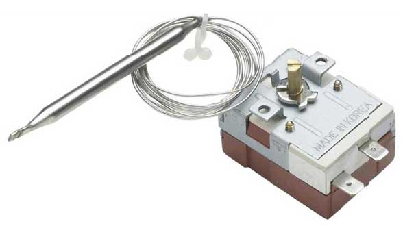
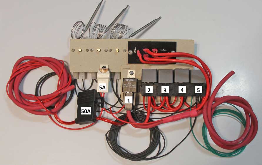
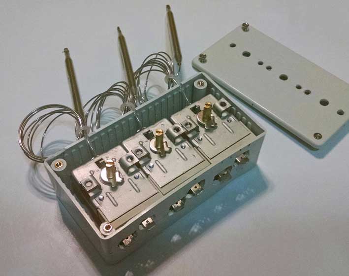
The below diagram will help some of you understand how this works. There are four relays (one for each speed), three temp sensors (for low, medium and high) and a manual override switch for full power (which is even higher speed). The Mark VIII fan on full power is really an amazing thing to see and hear. Very few cars will need that kind of air flow for normal use, but it's there if needed.
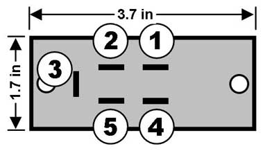
Dorman 973-018
By now some of you are wondering how the different speeds are regulated. That's done with an AC/heater fan resistor pack. The one I chose is Dorman 973-018 (shown below). Cost is under $10.00. It's a 4-speed resistor, but I am only using three of the speeds. More on that later.

4-Speed Controller Function Theory
The fan will remain off until your low temp set point is reached and the sensor activates power to the low speed relay (Relay 4). When your temperature climbs higher, the second sensor will activate the next relay (Relay 3), automatically cutting power to the lower relay. This way only one circuit will be on at a time. This action works for each relay in succession as temps rise and fan speed increases.

Why Four Speeds?
Why not? I know two speeds is definitely not enough for a Mark VIII fan. Three speeds might be ok. Four seems about right to me. The diagram here can easily be converted to a 3-speed harness by eliminating relay #4. Heck, you can even build a 5-speed harness using these components by adding just one more relay. But I just chose to do four speeds.

EDIT 09-16-2016: After creating this thread I created the following project page in my site: http://www.davebarton.com/fanharness.html

Comments or questions welcome.
Dave B.
 

Attachments

  • Dorman973-018-2.jpg
    Dorman973-018-2.jpg
    25.9 KB · Views: 369
  • 4speeddiagram1med.jpg
    4speeddiagram1med.jpg
    77 KB · Views: 366
Last edited:
Continued . . . . .

Below photo is the variable temp sensor I decided to try. I used three of them. It's Hayden PN 3653. Cost was about $19 each shipped on Amazon. It will work to trigger a positive circuit or ground circuit, either one. I chose to do ground circuits as you can see in the diagram.
Hayden3653.jpg


And more on that Dorman resistor pack. I tested the resistance through the four circuits and got the following results:
Dorman 973-018 Pinouts
1. Input: High Speed . . . . 0.3 Ohms
2. Input: Medium 2 . . . . . 0.8 Ohms
3. Input: Medium 1 . . . . . 1.4 Ohms
4. Input: Low . . . . . . . . . 3.1 Ohms
5: Output to fan
Dorman973-018-4.jpg


After getting my wiring diagram to what I thought would work, I built the below bench test model so I could see how it goes with the fan in the car. There are five relays because I added one (Relay #5) for the AC to activate a speed I liked. Relay #1 is the full speed relay to be activated by the override switch.

Relay #1 is 80 Amp capacity. I recommend no less for such a fan. The other relays are all 40 Amp.
4speedharness1-1lo.jpg


More shortly . . .
 
Last edited:
How about 0-100% variable? M.H. Yount runs the DCC controller and loves it. Hopefully there are other alternatives to continuous variable control....... in the future.
 
Last edited:
DCControl huh?
Long story why not. Short story is I have bought several and all have failed miserably. Last time I tried to order another my order went unanswered for 6 weeks while my car was down. He never, ever responded to emails and I never got my order. I had to file a Paypal dispute to get my refund. There are a lot of other people who have had the same problems with DCC. I can't imagine paying close to $200 for that.
Dave B.
 
Google finds similar stories.... and an equal amount of FORD guys that absolutely love his products. I don't own one.... but Yount has been thrilled with his. I'll delete the link since you've already "experienced" DCC.

Carry on!
 
I loved the DCC controller too until things went bad. It may be ok for small fans, but I think the big ones like the Taurus, T-Bird or Mark VIII fans are just too much for them. I got an average of 1.5 to 2 years out of each DCC before it fried. That was using a T-Bird fan. If he's improved them since, that's ok, but there's NO excuse for refusing to communicate with customers.

This project was born out of frustration over high-tech failures. I think my low-tech version will be much more sound. We'll see.
Dave B.
 
Continued . . .
Test results using my bench test model:
It's important to keep in mind that the fan was tested fully installed with a radiator, intercooler and AC condenser in front of it. It would likely pull less amperage with higher RPMs if it was tested out of the car and that would not be realistic. Tested with battery only (12.6v), engine off.

Resistor Pinout . . . . RPM (Percent) . . . . Amps Peak Spike/Constant Current
Fan full power . . . . . . 1800 (100%) . . . . . **35.2/33.6
1. High . . . . . . . . . . . 1400 (77%) . . . . . . 31.9/25.0
2. Medium 2 . . . . . . . 1000 (55%) . . . . . . 14.3/13.6
3. Medium 1 . . . . . . . . 650 (36%) . . . . . . . 8.5/7.4
4. Low . . . . . . . . . . . . 470 (26%) . . . . . . . 4.0/3.6
**Peak spike amps when ramping from 77% to 100%.

I considered using the 26% speed as my Low speed, but after feeling the air, I thought it was a bit too low. So I decided I would use the 36% speed as Low, 55% as Medium and 77% as High. Additionally I felt that the 77% speed would be a good speed for the AC.

The fan is whisper quiet at 36%. Can't even hear it over the engine.

More soon . . . Let me see some comments.
Dave B.
 
Last edited:
Flexalite 31165 variable controller works well- has a "soft" current ramp that decreases voltage spikes.

Ahhhh the Flexalite. That one lasted a bit longer than a DCC, but also fried (this was the most recent failure I had). While it does seem to have a soft start, the Flexalite is really only a 2-speed controller. 60% and 100% only. And as I mentioned earlier I don't want the 100% speed used for this big fan for normal driving (just there in case it's needed). And 60% is way too much fan for idling or cruising. And why run a fan at 100%/34 Amps if it's not needed?

I appreciate the comments. More are welcome.

If you think this is stupid, tell me.

Thanks, Dave B.
 
Last edited:
Continued . . .

Here's the three temp sensors going into a compact box so things will look tidy. I'll paint the box black.

haydenbox5lo.jpg


Dave B.
 
Last edited:
Dave, have you pulled any of these dead boxes apart to see what drivers they use, or how they're configured?

Ford fuel pump drivers are pretty cool, but also can't handle heavy loads and require PWM input. They have a big inductor in them to smooth things out and regulate noise.

To me simple would be a box with a conditioned input, a monstrously strong driver network, and a single wire from the ECU controlling it. (PWM or CAN)

Have you measured the max steady state current at 14.4V? Or the peak start up current when switched on with 14.4 supply? I'm curious as to how much your big fan draws :-)

PS, I love that my odo works! Thanks again! :)

I have not pulled any dead controllers apart. The DCC ones are all epoxy potted. Not sure about others. I wouldn't know what I'm looking at anyway.

I have only measured the fan current at 12.6v so far (engine off). Those results are already shown above (33.6 amps max). And I would not be able to get 14.4v out of my alternator anyway if that fan was on full. It's in the high 13's. I'll try measuring with the engine running once it's ready.
Thanks, Dave B.
 
Here are revised fan amperage figures at higher voltages (with engine idling). The fan pulls a lot out of the alternator, so testing at 14.4v will not be possible. And it sounds like a jet engine at 40A :-D. I don't have the Low speed (26%) hooked up, so all others are shown. My amp meter also shows watts if anyone finds it useful.

Resistor Pinout . . . .Fan Percent . . . . Amps Constant/@Voltage/Watts
Fan full power . . . . . . 100% . . . . . . . . 40/13.3v/530
1. High . . . . . . . . . . . 77% . . . . . . . . 29/13.6v/395
2. Medium 2 . . . . . . . . 55% . . . . . . . . 15.7/13.9v/217
3. Medium 1 . . . . . . . . 36% . . . . . . . . 8.6/14v/121

Dave B.
 
Here is a question from someone who employs caveman-level circuit design:
Would a ballast resistor made for stock auxiliary e-fans be more suitable for this application, albeit maybe only as a 2-speed or maybe by a pair of them and some fancy wiring achieving more speeds?
Who among us has not had to change a blower motor fan resistor group?
Sure, the failures are more obvious that an epoxied black box which might give different performance under operating loads than when continuity/resistance tested at the terminals...but still when I hear Dorman fan resistor pack in reference to improving reliability, I cringe a little.
 
Would a ballast resistor made for stock auxiliary e-fans be more suitable for this application, albeit maybe only as a 2-speed or maybe by a pair of them and some fancy wiring achieving more speeds?

A ceramic ballast resistor? I briefly thought about those. Don't know. Never played with one before to regulate a fan. Seems like it would take a lot of space for the same multi speed effect.
Dave B.
 
Neat project, hope it works (I see no reason not) How much $ do you have invested so far?

Once my car is back on the road I'll be using a $35 SPAL digital unit I bought on eBay, new they are in the $200 range and work well when working.

The failure is a bad design in which a fairly large capacitor is soldered too far from the board with nothing to prevent it from vibrating back and forth breaking a lead. <$5 later and a new cap is installed correctly.

I hada sal controller. Thought it was a piece of ****. every time I would get into boost and have a slight change in coolant temps the controller would freak out and go into limp mode and wouldn't turn on. Nathan had issues with his and he got rid of his. I talked to Spal tech support and they told me that they had no fix for this and I should remove my turbo.

Ive talked to Dave about while in the process of coming up with a solution for over coming shaddy pwm controllers and the one that almost left him stranded at Cars and Coffee when we were waiting in line to get in. This controller used basic off the shelf items that are known to work but I'm not surprised to see negative over positive in threads.

Whatever. I expect to see this in use in Daves car for years to come.
 
Back
Top