• Hello Guest, welcome to the initial stages of our new platform!
    You can find some additional information about where we are in the process of migrating the board and setting up our new software here

    Thank you for being a part of our community!

DET17's "Project cheap thrills" - '92 944T

The good news for any who follow.... you don't need to TIG the 4 bolt flange for the 960/850 NA throttle bodies to the B21F intake (as Nathan did to mine). I fit checked a standard B230FT TB to the original bolt 3 bolt pattern on the K-Jet NA intake, and it works just fine. With the TPS indexed downward (using the B234F parts I listed), it clears the intake just fine. I've got 3 more of the B21F intakes, in case you decide to convert.

A side benefit of the B21F intake.... there's more room to access everything below it. Starter, breather box, heater control valve..... all much easier to service.
 
Last edited:
A side benefit of the B21F intake.... there's more room to access everything below it. Starter, breather box, heater control valve..... all much easier to service.

I converted my b21f intake to efi and I've done many test fits and I love the fact that it isn't cluttered anymore. Here's a pic of mine powder coated(gold of course).

38240410046_e62a309f8b.jpg
 
Eurosport Tuning air box install

Happy 2018! Can't wait to get this project done.......

As purchased the air box was built to mount the stock 016 AMM. I'm going to run the 012 which is the larger 3" version. I considered some options to enlarge the original hole (variable speed jig saw, dremel) and decided on the latter. After fit checking my do88 intake hose, I decided to center the new larger hole on the original. Here's the air box with the larger hole roughed in:


Carefully free handing the dremel and HD cutoff discs, I got the AMM to just slide thru the steel hole. I mark the highspots in yellow wax pencil, so to finish the hole with the 120 grit mini drum sander on the dremel:


The turbo inlet hose is 3D sized for the factory 7/9 air box location, and is too long for the custom air box & mounted 012 AMM. I carefully trimmed the hose (after measuring at least twice) using a T-bolt band clamp and brand new utility knife blade lubed with soap & water (which cuts even the 4 ply hose with ease). With hose shortened to length, it's finally time to fit check between the AMM and the Mitsu 19t:


Got this smaller K&N filter onhand that I installed just for the pics; I will be purchasing a new filter with an OAL of approx. 10inches, 6 inch element OD (the limit of what will clear the sheet metal of the air box) and a 3" mounting inside diameter:


If you decide to use K&N, they have equations on their tech pages that enable you to calculate the CFM requirements of your engine, and then the filter fabric area required based on the design flow specs. I'll detail the calcs later, when I install the actual filter which will be used (K&N or other, yet TBD).

Lastly, the front mounting details of the air box. Note the aluminum cylindrical spacer which I believe was 13mm long after lathe turning. The bottom foot bolts directly thru the factory zinc plated mount for the OEM black plastic air box. Don't know who made these for EuroSport Tuning, but the fit check proves that it fits the 7/9 geometry quite nicely!

 
19t wastegate actuator KINUGAWA

Well this Saturday was destined for the wastegate mount to my 19t.

I guess it's fairly well known that the MITSU TD04 (15g or larger) family of FWD turbos don't have a commercial solution for the WG actuator mounting in the RWD application. I did a fair amount of research to see what others had done, and the most common starting point mentioned was using a later AC compressor mounting plate, in conjunction with other "bits".

I posted a thread months back about the 19t & WG porting; several suggested that the KINUGAWA actuator was a nice upgrade which fully opened the TD04 turbine wastegate (implied/inferred that the MITSU actuator doesn't fully open the gate). I found a nice 850 version which came with a mounting bracket that looked to be useful. I was recommended by ARD and others on SwedeSpeed to use ~ 4.5 psi spring in the unit for a 19t. I bought the smallest one that KINUGAWA offered which I think was near 5 psi.

Took the 850 bracket and cut off the portions I didn't need; dropped all the pieces in a muriatic acid bath to strip all the plating off and get it ready for welding. Here I'm mocking up the WG actuator pieces with a small C clamp:


Only one of the M8 threaded bosses in the 19t was of any use in the RWD application. After careful consideration, I decided the only real candidate (without TIG welding to the compressor casting) was to drill & tap the location of the serial plate. You better believe I took many measurements and drilled very carefully:


I've decided to use an M8x1.0 pitch "fine thread" in the softer aluminum, rather than the more standard M8 x 1.25 pitch thread. Will hit FASTENAL this week to get the bottom tap and the fine thread bolt. I MIG'd together my custom bracket after numerous fit checks; stopping and starting welds/tacks doesn't make for the sweetest looking welds, but it won't fall apart:


When function is 100% confirmed, I'll clean up the WG actuator mount a bit, then acid bath it again and finally electroless nickel plate it.... don't want paint on that compressor which will be plenty hot, I hope!
 
AW71 oil lines reposition

With the new air box and the planned addition of an "extra oil cooler" for my AW71, the factory bent 8mm steel lines to the radiator mounted oil cooler just won't do. With a fit check of all the pertinent parts, you can see here that the return line (the upper) passes right thru the do88 turbo inlet hose:


"No Good Condition!" is what my Japanese buddies would say. Anticipating a repositioning of the lines, I'd previously purchased a 5/16" steel tubing bender. While I didn't take any action pics of the process, I'll say that if you want a professional looking result, you simply must use a tubing bender. What I did was after disconnecting both supply and return lines from the radiator, then removing the "side by side tubing clips" that come with the cars, and finally disconnecting from the trans rear connection that longest (upper) hardline, you can wrestle it forward up around the engine mount so you can perform the bending.

If you want ANAL quality bent steel tubing, then buy a 2 foot 5/16" blank from NAPA and practice. There is a real knack to the use of these benders...... but suffice to say that you can twirl the bender around the 8mm (5/16") steel line and bend OR straighten it as you like. One tricky bit is up near the hex nut, you can only get so close to the nut and perform a bend (something like 60mm from the flare to the 90* down). Bust out those geometry skills! The joy is if you screw up, you can "mend your bends" with the tool.

Since this is a DD and I'm not obsessing about perfection.... function rules the day, but I tried to make the angles as clean as possible. Here is the final result, showing the connection to the "extra oil cooler" junction block. Special thanks to HiPerfAuto who supplied me we an NOS 240 cooler for this project (with a very cool picture of a 240 pulling a camper on the box :cool:)


As you can see, you've got to "thread the needle" just a bit to get this upper oil line between the big do88 3" AMM inlet hose and the hot side do88 charge pipe. It fits, and you don't even have to reflare the factory line! This is yet another example of "measure twice, bend once".

Soon I'll document the pics of the extra oil cooler install.... will add some holes to the front radiator core support for the hoses to pass thru and grommet installation to protect those hoses. Then there's a custom mount to carry the Setrab cooler. So much yet to do.......
 
A/C reconstruction in winter

Yep, as the schedule would have it. Been busy in the last week with all the missing lines and O-rings collected for the R134a system.

Quickly (as I'm hitting the road to tow my sons blown HG 745 4 hours back to GA :grrr: ) some of the details.

Comparison of my original '92 ZEXEL compressor, and the new SELTEC compressor (this style fits the 92-93 7/9s, maybe also the 91s). Note the funky twisted "suction line" which is required:


Spent an incredibly long time transplanting all the Volvo cadmium plated mounts & fasteners, hose line clamps, to the new compressor. All in all it was a royal PITA, but we must recall these compressors aren't brand specific and that Volvo had to design the mounting system. With the compressor set in place and a fresh set of IPD poly mounts to stop the dreaded belt squeal when the OEM stuff invariably begins to "sag and creep":


NOTE the blue ground wire in the lower right.... no ground to battery, no CLUTCH function! That was yet another scar/lesson learned..... the original wire isn't blue (rather it's black), but I used what I had, as previous hack mechanics had tossed it :wtf:. Read from your meter to the battery NEG post when installed.... if resistance isn't near nothing, your ground is NGC (no good condition).

More later.... go to saddle up and ride. Will post the specs of the actual hoses used.... they also are specific to 92- 7/9s, as the 93+ is a totally different animal.
 
I've enjoyed watching you transform this 940T into your own personal vision of what a 'grandpa' series can become, but I think at this point you have to rename it 'Project moderately expensive thrills'. LOL
 
Is that to say that the 93+ compressor and lines won't work if I put them into a 1990 740?

They will work, so long as you move the (1) mount for the compressor & alternator, (2) use a 93+ condenser, and (3) I can't be certain but the lines to the accumulator (the "suction line") just might work with your accumulator....however the suction and high pressure lines must match the 93+ compressor. I thought about going this route, but decided to stay with the 92 type compressor and just change to a variable orifice tube, which is known to improve low rpm performance of the A/C system.
 
I've enjoyed watching you transform this 940T into your own personal vision of what a 'grandpa' series can become, but I think at this point you have to rename it 'Project moderately expensive thrills'. LOL

Guilty. "Cheap Thrills" went by the boards, oh, somewhere around 2014 :rofl: I've got to drive this thing until I retire to break even!
 
LSD install in the 1041; A/C hose conundrum solved

Well I've been damn busy with expanded responsibility at work.... but finally got an evening to grind out some of the punch list items on the 940.

As I reported previously, I bought an DANA Power-LOK from Billy780 awhile back..... I was thinking about a TRUE-TRAC 588, but when this OE LSD came available from a 91 740, I bought it. Hopefully having an AW71 will protect those cross shafts.... only time will tell.

What I noticed when I pulled the LSD from the donor rear end, was it had some serious preload on the carrier bearings. Compared to the G80s I've pulled, this unit was really "in there". The green books state that carrier preload is between .006" and .008". I think these units must have been set at .008" because you had to leverage it out of the 1041 housing. I recall that Simon Babbs found the same thing on a couple of these that he harvested.

I targeted the .008" preload, and found with the proper bearings/shims installed I was unable to convince the unit (with greased carrier cones and dead blow hammer) to get it into position. I did some JEEP forum searching, and found much data stating the Dana 30 (which our cars share with certain Jeeps) are recommended to use a case spreader for differential install. I found a simple design on YouTube built by a Jeep lover up in Canada, and basically followed his design with a couple tweaks.

Here you can see the case spreader that I built from 1/2" x 3" steel plate, and some 5/8" B7 hardened threaded rod:


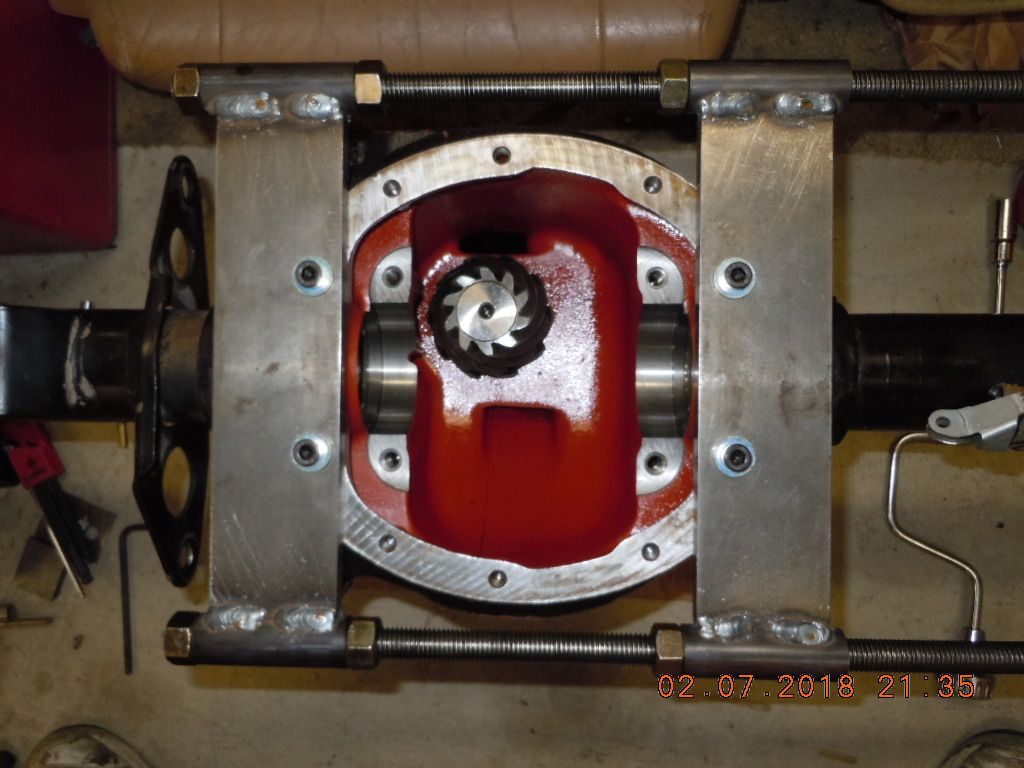
With the spreader installed to the four points shown (but floating, not tightly bound to the housing.... 1/4 turn back from snug) I installed my indicator:


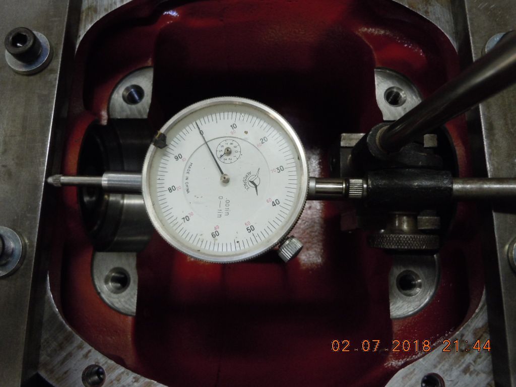
With the target of .008" spread, and an absolute limit of .015" which per DANA will deform the housing, I symmetrically opened the case:


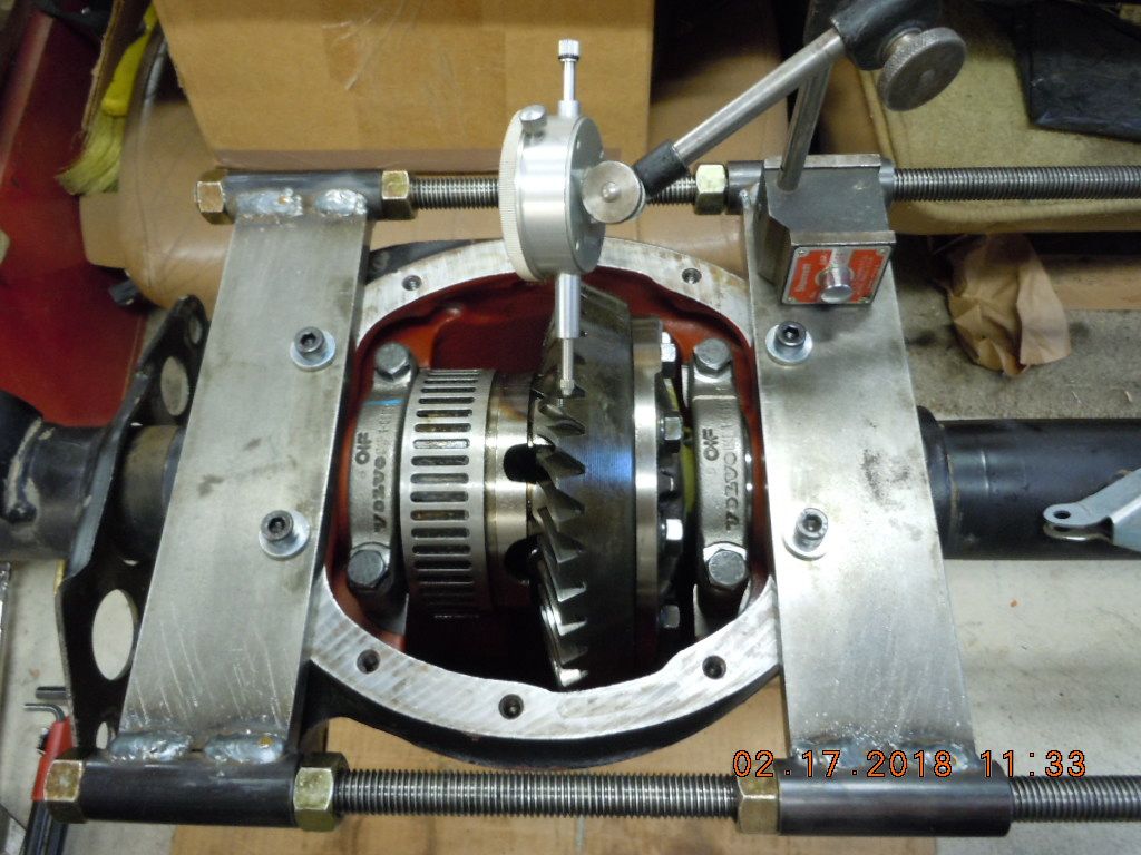
Once achieved, and the "proper carrier shims installed" :-P (which took multiple attempts), the LSD dropped into place. The 1041 carrier caps (match marked.... don't mix them up!) were torqued into place at 45 lb.ft. of torque.

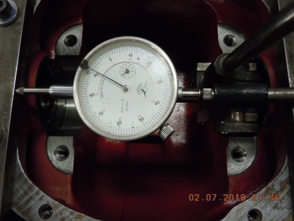
Done properly, the backlash must be confirmed unless you want to listen the rearend sing as you drive. OE specs are .005" to .007" per the green book (and a smidgen tighter per a 960 document I found online)...... I got mine to average .0065" and called it good! Here is the backlash checking:


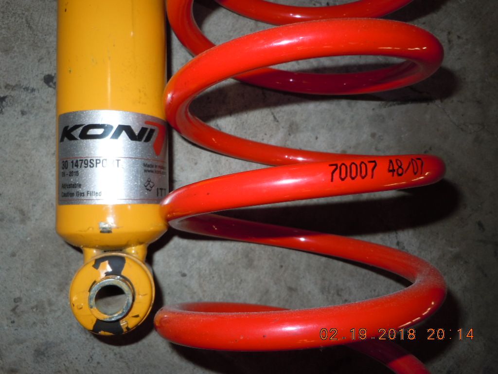
I spent last Saturday wrestling the rear end assy. back into position.... something much easier done with 2 people, but I got it solo. For TB posterity, here are my rear dampers and B&G Sedan rear springs:


I just ordered some GM limited slip friction additive.... 4 oz. is what is needed, along with about 1.6L of gear lube of your choice. I stayed with Dino gear oil..... as that is what these rear ends were designed for. Others claim the synthetics work just fine with these clutch differentials.... but I heeded the advice of Tom from "Tom's Differentials", a subject matter expert.

NOW with the 1041 back between the frame rails, I worked to finally complete the A/C reconstruction. With some details covered earlier, I basically bought a new compressor, condenser, hose sets, and variable orifice tube (for improved low RPM cooling). One item that bit me HARD in the bum was the suction line. I had a hole worn thru mine from a clamp, and had to replace the original. This didn't go well.....being a thrifty guy, I bought a China replacement from Four Seasons..... and it didn't fit worth a damn. I actually broke the hex nut at the low side attachment port on the compressor.....trying to use the wrench leverage to "walk it on" :grrr: Undeterred, I bought another one ($35, almost throw away priced).... and then spent another evening bending & massaging the damn thing to try and get fitment. I finally planted the SURRENDER flag on the second one after another fruitless evening.

What to do? Posted in wanted for a used OEM.... none turned up. Out of near desperation, I contacted a local Volvo parts shop called VOLUPARTS, and told them of the conundrum. Their response was simple: 92 940 A C hose Low pressure 91-92 only 940 USE # 1348538 instead of 3537731 ; 1373532; 3537901; 3522681

I looked over the webstore 3D illustrations, which are quite misleading. After an exchange of emails, Bill Eidson from VOLUPARTS said "stop overthinking this, it works!" Why not, I thought, and ordered.

Well tonight I installed their recommendation..... and it fits like a dream:


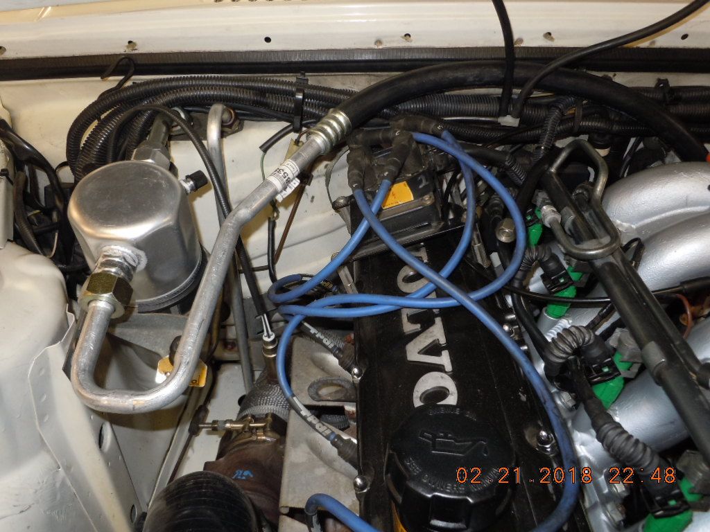
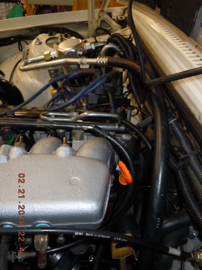
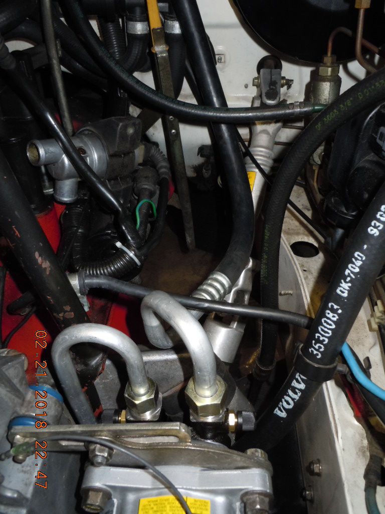
The damn thing works great! This P/N was stock on an 86-90 740, and the 780s, I believe.

As Homer Simpson once said.... "There is a time to think, and a time to act". I'm glad I listened to Bill, and plunked down my credit card. As of tonight, the complete A/C system is reinstalled, with POE ester oil installed in all the right places and volumes. Soon I'll bust out the deep vac pump and evacuate the system to confirm she's leak free.
 
19t inlet hose, 3" AMM, K&N filter

Another update.

Working to wrap up the exhaust side of the engine. The 19t has been installed for some time, but several of the supporting systems haven't been completed (and changed due to converting from the old T3 Garrett to the Mitsu 19t). I won't detail it here, but the suction side (return) water line had to be reworked and then the Hallman MBC lines connecting to the Kinugawa WG actuator also changed slightly. Happily, all were too long for the 19t and were shortened appropriately.

The BIG task for this afternoon was finalizing the do88 3"AMM inlet hose to the 19t. With the EuroSport Tuning air box, the hose had to be slightly shortened..... and then the "plan view" angle changed slightly due to the AMM being mounted to the air box and not the OEM air filter housing. These twists and slight contortions led me to buy CLAMPCO T-bolt style band clamps, to keep the damn thing from coming detached (this happened to my previous setup) under engine torque reactions.

After measuring twice, cutting once, it came out nicely:


I flipped the 3" AMM ( Bosch 012) so the connector is on the bottom pointing at the firewall:


This routed very cleanly, and plays well with the OEM connector and harness length from the main bundle on the fender.

Real CLAMPCO, Proudly made in the USA:


MUCH measuring and investigation resulted in this selection of the K&N filter which I'll use. As you can see, it just fits between the air box and the inside edge of the fender:


Haters of the K&N are gonna hate..... for some reason our Euro TB buddies have no love for the K&N oil cloth air filters. I searched high and low for some sort of a MANN filter that would have the 3" female rubber molded boot (to fit directly on the 012 AMM) and struck out. At the end of the day, I can't find any scientific proof that the K&N filters damage engines OR the AMMs....... but those that possibly did engine damage I suspect were (1) never oiled or (2) over oiled. Here is the PN for those that might follow:


RC-5106..... just add oil! ;-)
 
Yes, the resistor pack for the low Z injectors must be removed.

Up soon, sorting out mounting the IAC and hoses for same......and engine breather hose from the box beneath the B21EFI intake to the new do88 turbo inlet hose. I'm getting there......
 
Back
Top