• Hello Guest, welcome to the initial stages of our new platform!
    You can find some additional information about where we are in the process of migrating the board and setting up our new software here

    Thank you for being a part of our community!

Homemade Electronic Boost Controller

fullup1

New member
Joined
Jun 5, 2003
Location
Blacksburg, VA
This is for a mechatronics project at school.

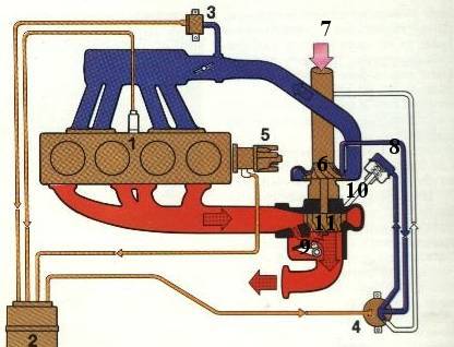
To ignore the specifics, the important question I have pertains to the wastegate pressure signal. I'm using a normally closed 3-way solenoid air valve to block the signal going to the wastegate, and I'm trying to send a PWM signal to the solenoid based on the desired boost specified by a potentiometer.

I have a Motorola MPX4250A pressure transducer for any closed-loop operation I want to perform, but so far I'm having problems just determining the PWM necessary for particular levels of boost.

As a for instance, I expect something like this:
100% duty cycle --> always open --> stock boost ~7.5psi
75% duty cycle --> 9 psi
50% duty cycle --> 12 psi
25% duty cycle --> 15 psi
0% duty cycle --> BOOM

Originally I tried to use the "error" between the desired boost pressure and the actual boost pressure to speed up the response of the turbocharger, but to no avail. I've considered using differential control by taking the error from two separate readings and based a PWM correction upon that, but I haven't even gotten the base PWM to work correctly.

Does anyone have any clever control ideas for how to determine what PWM signal should be sent to the solenoid? I have the necessary elements for closed-loop negative feedback, I just can't figure out how to force the output of the control loop to match the input (since I have no reference for how the dynamic response of the turbocharger can be modeled).

Any help would be appreciated.
 
Buddy, we're trying to figure that one out ourselves on www.msefi.com ... We've got an open loop function working fine, and there's a functional closed loop system but it's horribly flawed.

The way it works now is something like:

Error = target boost - current boost
Velocity = last error - current error

Next output = last output + (error x error gain) - (velocity x velocity gain).
(this is for a variable orifice boost bleed, not a boost signal blocker like you're using)

With my system, 40-45% duty holds the boost I want. However, the output goes to 100% duty long before my boost gets to the target. Once it blows past the target, it takes a while for the duty to come back down to where it needs to be. The idea of the velocity correction is that the faster the boost is climbing, the more the duty is reduced so it won't overshoot as badly. Well, that doesn't work so well in practice because as Error gets small, it becomes insignificant, but the velocity still has a major controlling effect: Once boost starts moving upwards, the velocity component overpowers the error component and it drastically drops duty. Boost starts to drop and again velocity overpowers error and it shoots the duty back upwards. The gain is supposed to allow you to tailor the strength of the velocity, but in order to have it mild enough to prevent oscillation near the target, it's not strong enough to have an effect on boost rise.

Suggestions to fix this include a user input cap on max duty cycle, so instead of getting all the way up to 100% it might only go to 50%, and it'll have a shorter trip back down to 40-45%. Another suggestion is to give Velocity and Error exponential control so that Error is much more important than Velocity when boost is slowly rising or falling but Velocity has a larger effect when it's really moving. One thing that DID help was to get rid of the Velocity component and just have a fixed duty cycle until the boost got to within a few kPa of the target, at which point it would just switch over to the closed loop system. Worked good, until we went to 6x6 TPS/RPM maps and it became too difficult to set up to be practical.

I've told you where we are with it, so please return the favour and if you have any progress, post it here or on the msefi website.
 
fullup1 said:
As a for instance, I expect something like this:
100% duty cycle --> always open --> stock boost ~7.5psi
75% duty cycle --> 9 psi
50% duty cycle --> 12 psi
25% duty cycle --> 15 psi
0% duty cycle --> BOOM
Wouldn't it be better to bleed of the pressure to the rather than blocking it and getting something like this:
0% duty cycle --> always open --> stock boost ~7.5psi
25% duty cycle --> 9 psi
50% duty cycle --> 12 psi
75% duty cycle --> 15 psi
100% duty cycle --> BOOM

Then if the unit fails the boost will be stock!
 
dr. volvo is right.

First of all, you have to wire the solenoid so it bleeds the WG-signal until engaged. Second, you need pressure transducer. Then it's just a matter of using a comparator and letting it compare transducer and reference voltage then modulating PWM or triggering solenoid directly.
 
Well yes, in hindsight it would've been wise to get a normally-open solenoid air valve and just control when it closes rather than vice-versa, but unfortunately there are only a few days until my presentation, so all of the particulars will have to be glazed over for now. Then again, we could just hook the solenoid up to bleed the signal going to the wastegate, but we've already got some code written to control it the other way. I guess the code wouldn't change much anyways, but we've only got a short amount of time to get this ready to present.

My group (there are 4 of us, but I'm somewhat of the driving force in this project) thought about trying to use a PID controller, with the PD being represented by what you talked about, and the I being added by taking a running average of the error. However, since this is only an 8bit microcontroller (PIC16F84A), we can only divide by numbers up until 255, and storing higher numbers becomes a matter of using two 8bit "words" to get a 16bit "word."

What we thought to do was to try doing a pseudo-average where we would just take the current average, multiply it by a large number, add the current error, then divide by the large number + 1. The problem with this is that we can't multiply by such a large number because we'll once again have the problem of numbers greater than 255.

Of course, all of this has to be done in assembly, and since the PIC is a RISC chip, we only have like 35 commands at our disposal.

Similar to what you've suggested, we thought that we would just leave the solenoid closed to raise the boost very quickly, then begin our PWM signal about 1.5~2 psi before the desired boost setting. Since the turbocharger's response is quite slow, that few psi "buffer" would be necessary to prevent overboost, but it sounds like you've already been attacking this problem for quite some time.

When you say that 40~45% holds the boost you want, you're referring to the particular boost setting you run in your car? So different duty cycles do actually correspond to different boost levels, as I assumed?

Thanks for all of the help, I'll be certain to post if we manage to get some semblance of control over the boost.
 
fullup1 said:
When you say that 40~45% holds the boost you want, you're referring to the particular boost setting you run in your car? So different duty cycles do actually correspond to different boost levels, as I assumed?
Oh yeah, absolutely. It's very controllable with PWM, but nowhere near linear. Below a certain duty it won't open the normally-closed valve at all, and the closer you get to 100% duty the less effect it has, as the valve is already able to flow more than the tubing leading up to it.
 
You can also use the setup with the solenioid you have and use a small adjusteable bypass.
Then you can adjust the bypass so the boost at 0% don't go over XX Psi.
 
You are attacking the problem that has been researched and solved decades ago. Worst of all, you are doing it the wrong way.

In order to have any sort of practical use:
1. This device needs to have feedback from pressure-transducer.
2. Boost must default to base boost in any case of malfunction.

Check SAAB APC system, for example, it's exactly same thing as you are building but built with analog electronics and with extra tricks available (tapering of boost at high revs, knock detection).

It's absolutely easiest to use standard three-way solenoid that defaults to opening the passage to wastegate when not powered. Wastegate has to be set to lowest safe boost, so called "base boost".

Then, solenoid is PWM pulsed (@ approx 20Hz) to bleed off the air going into wastegate and let it enter turbo-intake instead (not into atmosphere beacuse car will go rich).

PWM should be controlled by PIC and duty cycle should be derived from difference between transducer-signal and reference signal (with some bias added).

All this is A1 boilerplate automatic control engineering and I really hope your supervisor doesn't know anything about cars, beacuse your design is basically useless in any real-world implementation.

Harsh words, I know. but you should have researched the subject before you started...

Usual wiring of electronic boost controllers:
apc.jpg


3- transducer
10-wastegate
4-solenoid
2-boost controller device
8-wastegate pressure signal
1-knock signal (ignored in your case)
 
I think the best way to do this would be a simple PI or PID loop.. not sure how to do it fully in software anymore, but I've written them before. Seach for PWM and PID to get the basics off Google.
 
I don't know enough about turbo duty cycles, but I know more than I want to about digital logic circuitry and microcontrollers/assembly code, so maybe I can help.

To me it sounds like you need to run an opamp comparator circuit to find your delta value. I would think that the pressure sensor issues an analog output, vs. the digital representation of the desired value, so you may need a DAC to compare the 2 with opamps, or you could use an ADC (it'd be easier if that PIC had an onboard one) to compare the two in the PIC.

I'm not sure how you would need numbers greater than 255, but word operations aren't too hard. You'd be surprised what you can do with just 35 instructions.

There's probably more to this than I'm thinking, but if just need to monitor a real-time pressure and adjust it via sending out a PWM signal with a duty cycle corresponding to the boost pressure, it shouldn't be TOO hard.

Shoot me a line if you run into trouble.
I knew EE would come in handy some day...

_z
 
A quite interesting thread, i must say :)
Perhaps i can throw in a few cents,too. First off, i think a simple PI closed-loop control would be OK, at least for demonstrating functionality in a school project.
I recall that i have read that commercial EBC's use fuzzy logic to overcome boost peaking phenomena and give a generally better control.
Also, while a 1684F is a nice microcontroller (it having "only" 35 instructions is no limitation really, if you are a driven assembler programmer ;-) I would have opted for something with built-in A/D conversion as pointed out earlier. Now you either have to interface to external ADC's or do the actual error signal calculation using analog circuitry (op-amps etc) which more or less takes away some of the benefits of using an advanced microcontroller...
 
beepbeep said:
You are attacking the problem that has been researched and solved decades ago. Worst of all, you are doing it the wrong way.

In order to have any sort of practical use:
1. This device needs to have feedback from pressure-transducer.
2. Boost must default to base boost in any case of malfunction.

Check SAAB APC system, for example, it's exactly same thing as you are building but built with analog electronics and with extra tricks available (tapering of boost at high revs, knock detection).

It's absolutely easiest to use standard three-way solenoid that defaults to opening the passage to wastegate when not powered. Wastegate has to be set to lowest safe boost, so called "base boost".

Then, solenoid is PWM pulsed (@ approx 20Hz) to bleed off the air going into wastegate and let it enter turbo-intake instead (not into atmosphere beacuse car will go rich).

PWM should be controlled by PIC and duty cycle should be derived from difference between transducer-signal and reference signal (with some bias added).

All this is A1 boilerplate automatic control engineering and I really hope your supervisor doesn't know anything about cars, beacuse your design is basically useless in any real-world implementation.

Harsh words, I know. but you should have researched the subject before you started...

Usual wiring of electronic boost controllers:
apc.jpg


3- transducer
10-wastegate
4-solenoid
2-boost controller device
8-wastegate pressure signal
1-knock signal (ignored in your case)


Please post this on www.msefi.com and let them know the error of their ways, I'm sure they'd love to hear it there too.

Yes I know the PIC should be giving a PWM signal, and yes I know the duty cycle should be derived from the difference between the actual pressure and the desired pressure. In addition to this it would be helpful to base the PWM on the rate of change of the difference and on the running average of the difference (the D and I in a PID controller, respectively).

In school we don't have "supervisors," we have professors. If you could explain exactly what you mean by standard A1 boilerplate automatic control engineering, that would be helpful, since it's probably a lot easier for you to just say it than to actually solve this problem.

I know this problem has been solved before, but I'm not looking to simply copy another design, the point of this project was to come up with something remotely original. Yes, I could just yank a Saab APC system off a car at the junkyard, or I could go buy a boost controller for $400, but I thought it might be a little more fulfilling to actually go through the process myself so I would actually know what is going on (while learning a little assembly language and electronics in the process....ME's don't typically take EE related classes).

It's one thing to solve this problem in your head and think you know how it works, but actually attempting to control the wastegate using circuitry and software that you had to put together and code yourself is quite a different case. I'm not talking about an extension of MS so that I can tie the boost controller into the MAP vs RPM tables, I'm saying a completely separate controller that you just built within the past 3 weeks.

My point is that the turbocharger and the wastegate have a response that is tough to model as the "plant" in a control loop, and so finding the suitable P, I, and D components of a controller that will allow the system to remain stable, reduce overshoot, and respond very quickly is more difficult than you make it sound.

At this point I think that ditching the wastegate pressure diaphragm altogether in favor of a linear actuator would be a better idea. At least that way there would be no need to worry about bleeding off pressure signals using PWMs, but rather the relationship between the signal to the actuator and the boost would be much easier to determine.

I'm not saying I know it all, I'm saying that I think you should be a little more understanding until you attempt attack this problem on your own. If you've already got a valid controls solution, then by all means post it and I'll be quiet. Give specifics as to how you've determined what PWM to use for what difference in pressures, as well as the "some bias added" that you refer to, and I'll give it a try. Otherwise, please don't attack me like I'm some sort of invalid who has no idea what's going on. I was looking for help so I asked some questions.
 
fullup1 said:
My point is that the turbocharger and the wastegate have a response that is tough to model as the "plant" in a control loop, and so finding the suitable P, I, and D components of a controller that will allow the system to remain stable, reduce overshoot, and respond very quickly is more difficult than you make it sound.

That was more or less what i said in my post, commercial EBC's does not use PID regulation from what i know. These are the typical flaws of classic PID, they respond poorly in complex systems and you have to adjust (manually or automatically) the parameters continously too keep the system stable. (Stable and "respond very quickly" is almost an oxymoron for PID systems :-P ).

Thus, you might have to implement some sort of tuning and/or just try out a suitable set of parameters using practical testing.
As i said you might be better off to make a PI (skip the derivate). The D doesnt add a whole lot and you have one less parameter to bother with...
 
Last edited:
PI loop is probably enough. I would skip PWM just to be different.
What would be nice is to get a vale whose aperture varies with voltage linearly. More expensive valve but everything need to be broken into linear units if you're really going to vary boost in a quantitative way. So, variable ap spool valve in line w/ the wastegate diaphragm line. In parallel with this (or any valve) should be a ball type poppet valve pointed AWAY form the actuator (ie so it will only flow towards the manifold. You need this so that when you let off the throttle, boost trapped in the wastgate can vent back into the intake so the wastegate will close between gearshifts, etc so you get good spool when you get back on it.
OK so the valve can be driven by an 8 bit D/A converter into an Op amp set up with a knob for gain. Now you have a knob to tweak how far the valve closes for a given output voltage.

Now you also need a pressure transducer- idealley with a semi linear response as well as we need to compare this reading to the current output to the D/A. So this works opposite way. transducer to op amp set up w/ variable gain into A/D converter.

Now you can determine manifold pressure linearly with an absolute value of 0-255 and you can modify the output to the wastegate bleed linearly 0-255.

Now you have two values that you can actually do some math on. And not only that, but you can vary the gain for each value independently without reprogramming the chip. Basically you would set the gain from the tranducer so that the voltage goes fullscale/5v/255 at say a few psi beyond what your intended max boost pressure might be and then you just leave it really.

On the valve output you adjust it so that 255 loaded into the D/A gives you max boost. Sorry for what is probably mostly painfully obvious.

So basically aquire the A/D sample on a constant interrupt, at which point you save the value into an array of an arbitrary number of variables, say, oh, three- T1,T2,T3. After each aquisition you shift the data ahead so you always have the last three points.

At this point you'll just have to play with the actual algorithm. Basically lots of comparisons to work out the slope. You can then use this as a gain factor when computing the current-goal=error. At that point the required change is error*gain.
You could take the slope of the last two or last three data points and do PI or you could compare how the slope changed between T1,T2 and T2,T3 and then correct for increaing/decreasing slope and add the derivative elemnt. I'd try to just get it working with slope.

I was a Robotics and Automation Technologist before I got so volvo obsessed that I gave up on having a real job. lol. My final project was a 4 axis breath (pneumaticall) controlled robotic wheelchair arm so there was some pnmeumatics and motion control onvoled. Sortof crosses over. Never thought about a boost controller till now. Sure there's lots of holes in this such as I never accounted for signed numbers etc but I hope it furthers your thought process!
 
Also yak, I think what you say about PID stability is true if you are trying to keep an unbalanced system under control with just software, but if the valving and sensors are setup properly before digitization then it's much easier to control how the system is damped on the fly.
 
fullup1 said:
At this point I think that ditching the wastegate pressure diaphragm altogether in favor of a linear actuator would be a better idea. At least that way there would be no need to worry about bleeding off pressure signals using PWMs, but rather the relationship between the signal to the actuator and the boost would be much easier to determine.

I am not so sure about that. Replacing the wastegate actuator with a servo of some sort might remove one of the issues, but as you write, you still have the transfer function of the turbocharge (and the rest of the engine) to deal with. These are quite nonlinear systems, too. The amount of exhaust for example, how does that vary linearly with pressure in? There is also another factor involved here, which position the throttle is in. What i am thinking here, we have a system here whose characteristics change over time, so we need a control algorithm that can adapt.
I think if you analyzed the entire system f(x), from exhaust pressue and speed (that drives the turbine) to intake manifold pressure, you'd find it to be very complex even without the wastegate.
 
Last edited:
yea but you're not trying to model a system per se. In order to get this off the ground and working well enough for a presentation (and ideally so a furtherance of knowledge is achieved that could be applied towards a cheap boost controller or rolled into the megasquirt project) you need to boil it down to the basics and the build upwards from there. In this case the objective desired is a set reading(or readings) on the map sensor, controlled by a flutter valve or linear actuator.

You're correct in that one cannot apply a linear formula to wastegate function, its at the very least exponential and possibly factorial in nature to the point where small changes in distance traveled by the actuator bring about large changes in the map sensor reading. So what you need is something that can keep a very close watch on what the map sensor is seeing, even an 8mhz processor shouldn't have any problem watching the map signal several times a second and applying that to minute changes with an LA.

with the standard wastegate actuator the potential problems are a less than instantaneous reaction (which could and probably would be mis interpreted by the controller) throwing everything off and the net result being bizzare boost fluctuations/etc.

I can forsee a couple problems using an LA, however, the general rule of thumb with turbo systems is for every psi you have in the intake you've got at least 2x that in the exhaust, you'd need an actuator thats capable of handling that kind of pressure and still maintain accuracy, and be somewhat temp resistant and fit in the space available (someone else is going to have to jump in here, I dont have any experience with LA's, this speculation could be completely off base).

Instead of pwm%'s for boost, you might want to use kpa values instead as this would make comparision a bit easier and when the boost comes within say 15 or 20 kpa of the target you could have it tapper out a little to avoid overshooting. another thing to consider is, at least in my ms datalogs, even when you're at a certain boost level, its really moving around a little bit, so you might also consider putting in a +-5kpa "buffer of nothingness" where it doesnt make any change as long as the current kpa is within this range.

food for thought (i hope).
 
Hehe...let's calm down now and look trough few base demands fur such system, if used in real word.

1. System needs to default to base-boost in case something happends to boost-controller. That means solenoid has to be powered-on to "bleed" the wastegate signal line. Risk of loosing power or bad contact is much bigger than risk of solenoid getting stuck recieving full-on signal.

2. In case of full boost-controller failure, either electric (power-transistor failure) or mechanic (crack in signal-line going to wastegate) there should be "last resort", saving the engine from overboost.this is usually solved by adjustable pressure-switch wired in series with fuel pump, cutting fuel flow in case boost runaway. Trigger-pressure should be adjusted to value typicaly higher than max allowable boost.

3. Bled air from signal line should be recirculated into loop after AMM or you will be dumping alredy measured air, leading to rich condition.

4. Your boost controller must have feedback and run closed-loop. My understanding is that you designed open-loop system and that's main reason of my scepticism. Problems with open-loop system are many. First of all, PWM duty cycle is highly nonlinear to boost pressure. Even if you construct some sort of lookup-table (trough painfull trial-and-error) that would fit your particular car/turbo combo it will be unreliable and vary depending on exhaust backpressure (clogged cat?), air temp, turbo shape etc. As soon as you try it on another car it would need re-calibration. it's much easier and cheaper to design adaptive system used closed loop.

5. PWD is nothing to be afraid of. Solenoid can be either open or closed, so PWM is just a way of modulatig a flow trough it. PWM frequency values vary depending on which solenoid and bleed rate is used, but values between 16 and 50 Hz are typical.

6. P, I , D-values arent so critical one you have feedback signal. Generally, you'll be keeping wastegate shut until desired boost is reached, there is nothing else boost controller can do to speed up boost buildup cept that. Once boost floor is reached and comparator flips, it's a matter of keeping that boost where it should be. Using P-regulator only would result in slow overswing of boost to value sligthly higher than adjusted. Of course, I and D should be used but system itself is actually quite stable as turbo has lots of intertia.

Actually, just on-off switching of solenoid when treshold is reached is sufficient if only goal is to keep boost-pressure in check. This works and is used when constand boost level is desireable and no in-flight adjustments needed. It's usually solved by mechanical devices (look for Daves-device, for example).

Electronic boost controllers are used when you have need to dynamically alter boost during driving or have other special needs. One of most common is to taper boost at higher revs to prevent turbine overspeeding and heat buildup.

Most turbochargers used on customer cars slightly small (to give good response and mid-range torque) and cannot sustain equal boost at higher revs. That's why boost is tapered higher up. Second reason for tapering boost is beacuse acoustic knock-detection systems usually do deaf at higher RPM's so boost is adjusted down just to keep it safe.

So once again:

- Trying to make open-loop electronic boost controller is unwise, as solenoid duty cycle will vary wildly depending on array of external factors. Feedback sensor is very cheap way of making such device self-adoptable on wide array of engines.

- Transient response of boost buildup is slow due to turbocharger inertia...there is very little to be won by fiddling with PID if constant boost level is all you want.

- If constant boost level is all you want, mechanical device is cheapest way ....


I'm aware that I'm looking at this from purely practical standpoint and that you are doing it as extension of your studies/purely academical. ;)
 
What about lookup tables on the PIC? Using tables means that you can set the order of response - linear or otherwise. Just find a PIC with enough program space - the 16F628A i'm learning on (VERY similar to the 16F84) has 2K of program space, comparators, PWM, 3 timers... etc, so it's a pretty good buy. 20MHz operation would be ample.

That three day deadline sounds horrible.

Good luck!
 
Back
Top