• Hello Guest, welcome to the initial stages of our new platform!
    You can find some additional information about where we are in the process of migrating the board and setting up our new software here

    Thank you for being a part of our community!

Yet another wiring to fuel pump issue on a 84 240

joedirt

New member
Joined
Aug 6, 2017
Location
Beacon Falls, CT
Bear with me...this car a 5.0 swap in it to make things more confusing. It did run at one point, I believe a year or so ago.

Im getting zero fuel at the rail I know this much so far. Im starting with testing the in tank fuel pump wires as ill be replacing it after I actually get voltage to the connector.

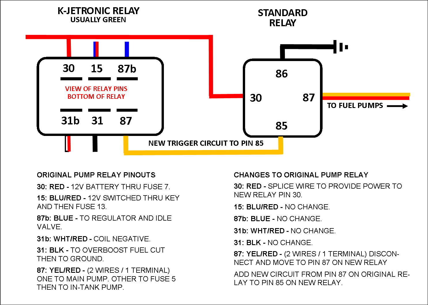
Im reading up on http://cleanflametrap.com/transferPump.htm and I was wondering if anyone had any info on the relay or relay's in my car that run the pumps? Such as what terminals I should be getting 12 volts to?

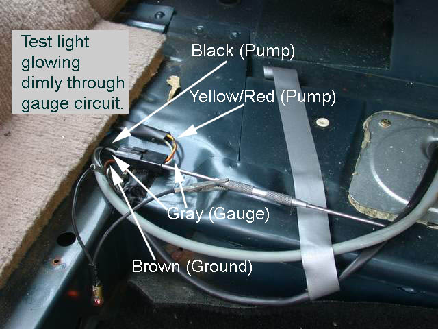
Going by this picture i'm not getting any voltage on the black wire I should be. Although I cant remember now if there was a Yellow/Red wire on my connector...
image010.jpg


Either way im hunting around for any wiring diagrams I can find on the path of the fuel pump wires if anyone has a link or photo id greatly appreciate it :zeeall: I didnt dig into the fuse panel yet either, which I will check first before ripping apart the dash to find the relays.
 
http://www.davebarton.com/

I think you will find your info here. You might have to dig a little. Another good site is www.cleanflametrap.com

Thanks for the links..

I feel like im getting closer, if I understand the fuel relay circuit correctly power would come from the relay to the fuse and then to the fuel pumps.

If thats the case then I found voltage coming out the fuel pump relay pole #87 with the key on, but its not making it to the in tank fuse #4. Im working on tracking down a wiring diagram to make sure its a straight shot from the relay to the fuse box.

12627d1453402565-fuel-pump-issues-fuel-pump-relay-diagram.png
 
Could be a K-Jet car or an LH-Jet car in '84. The fuel pump relays are in different locations and they're not the same relay.

If you found a green relay under the dash, it's a K-Jet car.
 
Using an oil pressure switch to complete the ground circuit of the fuel pump relay is an option. Fuel pump wouldn't work unless engine was cranking or running.
 
My V8 conversion fuel pump relay is in the right hand side rear wheel well on the wagon.

You are going to have to carefully document the intended operation of your particular conversion.

Tell us a little about your setup and we will try to help.
 
My V8 conversion fuel pump relay is in the right hand side rear wheel well on the wagon.

You are going to have to carefully document the intended operation of your particular conversion.

Tell us a little about your setup and we will try to help.

So I did locate a green Volvo relay under the driver side dash. Did not pull the glove box out and apart though to find another relay, I certainly will though and check it out. So I take it had a K Jet car lol?

The V8 conversion was done 2 owners ago give or take. It appears to be legit and done cleanly I believe it was a converse conversion. I believe with converse they used both the Volvo fuel pump relay and also the ford relay. The car did run at one point in its life.

Stupid question would the K jet cars fuse only have voltage if it was cranking over? I never bothered to check it while cranking.
 
Here's the wiring diagram for 82- turbo 240. The fuel pump relay gets power all the time through fuse 7 and power from the ignition switch through fuse 13. The relay powers the main fuel pump directly (or it used to), but the in tank pump is powered through fuse 5. The relay closes the contacts when it sees a signal from the coil.

Check that terminal 31 on the relay has a good ground. Originally, there was a boost pressure switch that would cut the ground signal to the relay in the event of over boost connected to this terminal.

82-TurboWiring.jpg

Thanks for the tips. Turns out my car is actually a 85 and it makes a difference as there is no wiring going to the #5 fuse at all its just vacant. And the power wire for the intank goes to #4. I even confirmed this by jumping power to the #4 and seeing voltage to the intank connector.

With the relay in place at the connector of it, im seeing power where there is supposed to be power. Also on that black ground I see it going to the boost pressure switch and it does appear to be a good ground at the time of testing. The switch shouldnt be any issue the car isnt boosted anymore but I dont need it so im thinking about removing it completely and just running a clean ground to the fuel pump relay instead.

I believe i've boiled it down to the lack of power from relay to intank fuse. There seems to be some kind of disconnect between the relay and #4 fuse. And there might be another Ford fuel pump relay in the mix since this is a swap car, hearing from TestPoint Ill have to look around in the area he was talking about in the rear wheel well. Ive also found that people are saying there is a relay behind the glove box as well which I havent looked for yet. Its confusing as hell honestly lol.
 
Also found this info regarding fuses being powered from other areas which I will be taking into consideration when I dig around.


I hope this thread helps somebody out in the future

https://www.matthewsvolvosite.com/forums/viewtopic.php?t=29499

I think you have misunderstood the "bridging" reference. Several of the fuses on your car are powered by a shared lead to reduce the number of wires entering the fuse box. Fuses 11, 12 and 13 are powered by one white/red lead.

Carefully check fuse 13 to see that it is working. If in doubt test it with an ohmmeter. Also check the contacts the fuse sits in as they are prone to oxidation.

If fuse 13 is OK you can run an easy test on the relay by putting your finger on top of it as you switch on the ignition and then turn the key to the crank position. Either when the key is moved to the "on" position or when the starter engages your fingers should feel a click. If not, remove the relay and inspect the connections. If corroded or overheated repair and reassemble with a new relay to recheck the operation, if the system is still not functioning properly proceed to next step.

Connect a test light or multi meter to earth (ground), usually a black lead. Turn the ignition key to the ''on' position, but leaving the engine off, and remove the relay. Using the other probe from the test light or meter test all terminal sockets in the relay connector, two out of the four should have power. If power only exists at one terminal or no power exists re-check related system fuses. If all related fuses are ok and you still have no power a wiring diagram from a car repair manual is needed to trace the wiring back to the power source to be repaired. If ok proceed to next step.

With the ignition key in the "off" position take a small piece of wire (14 to 20 gauge) and strip it on either end. Insert each end of the wire into the 87 and 30 relay block terminals and turn the ignition key to the "on" position. The relay is now bypassed so you should hear the pumps working.

You can find which of the terminals are 87 and 30 by looking at the underside of the relay or at the diagram printed on its side.

If the pump doesn't work when you bypass the relay post back for further tests before assuming the pumps are the culprits.

Bill.
 
The woes of buying someone else project lol....

I pulled the fuse block and found that one side of the #4 fuse was even connected. So it only had a connector running back to the in tank fuel pump. I cant see any lose wires or connectors anywhere :grrr:


I was getting a solid 12 volts to the inline pump with the Key on. So I said to myself, self you're just gonna run a single intank pump anyways. I pulled the wires from the inline into the car and im gonna run those wires to the in-tank pump ignoring the smaller gauge wires going to it.

It does send 12 volts to the inline pump constantly with the key on though, I know on most cars it does prime and shut off until cranking. Not sure if that will be a issue.
 
Quick update:
After saying screw the stock ford fuel pump relay and also the volvo relay I sucessfully ran my own.

Ended up using a generic 4 pin relay (bosche Style) with a connector meant for it.

Ran a 12 gauge fused power wire from the battery to relay
Key on source from the fuse box
Ground from Pin 22 on the ecu which is the stock fuel pump trigger to ground the relay
Lastly a 12 gauge wire tied into the main pump wire going now going to the in tank DW200

Super simple and easy to troubleshoot if need be now. Def a great learning experience and the fuel pump cycles on momentarily when keyed on and after turns on when cranking and running.
 
Back
Top