• Hello Guest, welcome to the initial stages of our new platform!
    You can find some additional information about where we are in the process of migrating the board and setting up our new software here

    Thank you for being a part of our community!

Tuning the M1.8 ecu (pre-95 960), an experiment.

Broke4speed

Well-known member
Joined
Oct 5, 2009
Location
Marionville, Ontario, Canada
I'm a decade or so too late, and maybe someone's already done it, but I can't find any of their work...so I'm going to post my own. I like deciphering early Bosch ecus, and when a 94 960 popped up in one of my local yards, a swap project was born. I plan to wire it up using the stock ecu and tcu (minus the torque reduction wires), and flesh out the file with an Ostrich emulator. There will be no boost, but I don't see why there couldn't be, once I'm more familiar with everything.

I've put some of my XDFs up on the tunerpro website (M2.9, OBD1 VW ABA, and VW Digifant 1 G60), so I'll be sharing everything I learn. Whether or not anyone uses it doesn't matter, I just like doing this :).


The first thing I've discovered is that if you can find a copy of "Motronic Suite" (when you do, run it in admin mode), there will be M1.8 (pre-95) bins, and the software can convert the hex into maps already. It can only describe a few of them, but the raw data is all there. It looks a bit like BMW M1.7, which has part-throttle/idle mapping and separate 1x16 WOT maps for both fuel and ignition. With the realtime emulation function of the Ostrich, it's easy to trace the maps while running, so I'm currently transcribing everything over to Tunerpro to make an XDF.

I've pulled the bin out of the ecu I got at the junkyard (and the entire engine...but that's not the focus yet), and am using it as my base, but the other bins I've found are very similar. Just a bit of an offset between files, so the same xdf will work with adjustments. When I have a bit more of the transcribing done, I'll post up what I've got. I'm hoping to stumble upon the checksum info somehwere, so if anyone has any tips, it would be much appreciated. Too bad there aren't any ebay 'tuner' chips, they're always good for comparing and reverse engineering :).

See the last post for the XDF and bin.
 
Last edited:
Hmm...can't find any concrete info on the checksum, but I did find a document that describes how M1.8 works (although if you can't read french, it doesn't help much, lol). It does describe the various limp modes though, and it doesn't look like a missing speed signal is a terrible thing. I'm still trying to figure out a way to get the computer what it needs, but since I'm not running a 960 speedo, the speed signal might not be available. I can fake a 12v square wave pretty easily though, if need be.

http://en.calameo.com/books/0028413558bc9ef8a7643
 
One of the things that's been bugging me has been the whole 'speed sensor' nonsense, and whether or not it's a critical component of M1.8 or not. I can say for certain that it isn't on the later M2.9 I've worked with, but it's never a good idea to overlook a sensor input...just in case. Luckily, there is a bit of info out there about what type of pulse the ecu needs, so I can work with that.

The 48-window wheel in the diff sends a pulse to the 960 speedo, and it splits it off. A 48-pulse signal goes to the ABS, and a 'fabricated' 12-pulse signal goes to the ECU (possibly TCU as well, but not clear yet). The raw VR signal from the diff is conditioned by the speedo to look more like a square wave, from what I understand. I don't want to go through the hassle of mounting the 960 speedo as a standalone unit just to get the signal I need, and I already have a nice GPS speedometer, so I started looking in to how to get a proper pulse. I found this from 2010 on a Haltech forum:

Greetings all, i felt like posting this to give people a little bit of insight on the calibration of their speed sensor inputs. All it takes is a little math.

To determine the number of pulses per km the ECU requires in the speed sensor calibration field, we first need the number of teeth that our trigger wheel, transmission, wheel hub teeth, etc., has. For this example, we'll keep things simple, we'll pretend we've got a wheel sensor with 8 teeth around it.

We also need to determine the circumference of our tire, in order to know how many pulses per km the sensor will read. So, on this example, lets make it a 27" tire diameter.

Our formula for calculating the pulses per km can be summed up like this:

P/Km = 1000 (meters in 1km) / [ (pi * diameter) / # of teeth on sensor ]

So, in this example with our 27" tire we must convert 27" to meters to keep things in the same unit system (metric), so multiply inches by .0254 to get meters.

P/Km = 1000m / [ (3.1415 * .6858m) / 8 ]
P/Km = 1000 / 0.2693
P/Km = 3713 <<<< This is the number you will put in your pulses per km field in the Calibration tab for the vehicle speed sensor.

So, my rolling diameter is 24.9", and I'm looking for a 12-tooth signal. The math works out to 3765 ppm (taking into account the difference between KM and miles)...which is close enough to 4000 ppm that I could actually get away with using a cheap GPS-to-pulse signal converter. It should be close enough to keep the ECU from freaking out. If anything, the speed cut may kick in sooner than it should, but I highly doubt I'll ever go fast enough to trigger it anyway.
 
This is awesome. Very interested to see how this goes. I have a 95 960 thats 1.8 and i have an ostrich as well.
 
Huh, I guess I'm not alone, haha. There's always a point where I start to wonder if I'm crazy and should just let dead horses lie. Especially with decades-old technology.

I've been going over the wiring diagrams and I'm pretty confident that I can wire it in with my eyes closed. I'm going to do a bit more work on the XDF tonight, since my wife split for a girl's weekend today (she likes to start early...) and I have lots of time to spend doing car guy things :).
 
Im hoping to put a manual trans in my 95 960 1.8 at some point so its gonna be pretty necessary to remap the ECU and disable the auto trans checks as well.
 
Checksum is 16 bit sum up to 7FFC and stored at 7FFC.
It's not very important.
 
Got your PM, thanks a MILLION! :)

I wondered about the checksum, whether or not it was a sum of the whole file, or just a block, so that helps too. Even if it's not important enough to disable the ecu, I like having all the loose ends tidied up.
Dude, you rock!
 
I dismounted a cheap KKL interface today and removed the CH340T serial to USB chip.
TX and RX was then connected to a Teensy 3.6 with enabled 9-bit serial mode at 187500 bps
Motronic 1.8 will supply four values (8 or 16 bit) from RAM close to 100 times per second.
It is also possible to read single values by request, but this will be a bit slower.

At 4800 bps reading ROM takes about 40 minutes or so.
At 187500 bps this should be possible faster, but will require capable software on the PC side.
I hope to have this ready within the next 10-20 years.
 
Great! We're on the same timeline, lol.

I've been poking through the file and comparing some of the maps to other versions of motronic that I've worked with to try and decipher their possible use. I believe I've found an EGR duty cycle map, and possibly a WOT fuel table. BMW M1.1 and 1.3 use a strategy of a 1x16 map for WOT fuel and ignition conditions, which is what I think M1.8 might use, although the map I'm considering is only 1x8 or 10 (can't remember). The RPM spread is from idle all the way to redline, and the values climb to typically over-rich conditions, which is an OEM hallmark for 'safe' tuning. Won't know until I can try tracing it though. I really need a 960 as a daily until I get my engine swap done, haha.

Other versions of pre-torque model Motronic have 3D fuel maps for idle/part-throttle/and WOT conditions, but M1.8 seems a LOT simpler than those that I've worked with, and have very few large 3D tables with fuel values in them (or timing numbers that make sense). I'd love to find the rev limiter too, but that's a bit harder. Typically what I do when learning a file like this is to create a map in tunerpro that targets the main map address table, get the car up to operating temperature, trace that table while running a screen recorder to see what maps the ecu targets at various events (idle, cruise, WOT, etc). That helps to narrow down the uses of the various maps, and makes it easier to tune. Once you know what you're looking for, and what the ecu uses, you can easily re-address things and increase the size of the maps if you want. On M2.9, I've compiled all 3 fuel maps (Idle/part-throttle/wot) into a single 32x32 fuel map, and tuning is dead easy that way.
 
I can't find my old files, so starting fresh.

Here is one rpm check for 6990 rpm.

code:00000A97 code_A97:
code:00000A97 mov A, RAM_4B
code:00000A99 cjne A, #0xE9, code_A9C ; 0xE9: 6990 rpm
code:00000A99 ; cjne operand1, operand2
code:00000A99 ; The Carry bit C is set
code:00000A99 ; if operand1 is less than operand2,
code:00000A99 ; otherwise it is cleared.
code:00000A99 ; Meaning C is set if RPM is below 6990
code:00000A9C
code:00000A9C code_A9C:
code:00000A9C jc code_AA6 ; Jump if C=1. (RPM is below 6990)
code:00000A9E mov A, #0x14
code:00000AA0 mov R0, #0xF3
code:00000AA2 mov @R0, A
code:00000AA3 ljmp code_CB1

Another check for 0xF0 (7200 rpm):

code:00001CB7 code_1CB7:
code:00001CB7 setb IEN0.6 ; Interrupt Enable Register 0
code:00001CB9 setb IEN1.6 ; Interrupt Enable Register 1
code:00001CBB mov DPTR, #0xA040
code:00001CBE setb RAM_29.3
code:00001CC0 mov A, RAM_29
code:00001CC2 movx @DPTR, A
code:00001CC3 clr RAM_29.3
code:00001CC5 mov A, RAM_29
code:00001CC7 movx @DPTR, A
code:00001CC8 mov P2, #0
code:00001CCB mov R0, #1
code:00001CCD mov A, RAM_4B ; 7200 rpm
code:00001CCF cjne A, #0xF0, code_1CD2
code:00001CD2
code:00001CD2 code_1CD2:
code:00001CD2 jc code_1CD7
code:00001CD4 clr A
code:00001CD5 sjmp code_1CD9
 
Last edited:
Extended version of 8255A sounds very plausible. !!

TA13255A
I0: ECU pin 50: Ignition retard bit 1
I1: ECU pin 51: Ignition retard bit 0
I2: ECU pin 44: not used
I3: ECU pin 54: not used
I4: ECU pin 42: Drive/Neutral
I5: ECU pin 38: not used
I6: ECU pin 40: AC Coupling solenoid
I7: ECU pin 41: AC request from ECC
 
I put together a small document that compiles the M1.8 pinouts for the ecu, maf, tps, and CMP. I usually do this sort of thing to make swaps easier for myself, so why not share it.

[edit] Corrected mistake and re-uploaded as a PDF. I had incorrectly labeled the VSS pin as an output, when it's an input from the speedometer.
 

Attachments

  • Motronic_1-8_pinout.pdf
    41.9 KB · Views: 32
Last edited:
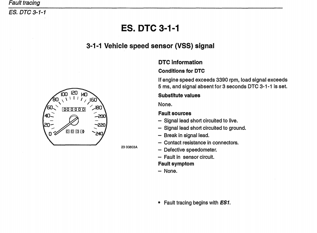
From what I've been reading, it looks like there is absolutely no consequence to leaving the VSS signal out of the ECU, with the POSSIBLE exception of a speed limiter that kicks in too soon and some cooling fan stuff when the AC is active. The M1.8 documentation doesn't say much about it, so I may leave it out until I have 'proof' of it's need for a swap.
 
Based on how LH2.4 works, I'd guess that the Vss signal is also used to help with decel fuel cut and entry into closed-loop idle control. If you have an automatic, it may not matter much.
 
According to the Motronic 1.8 green book, there's no conclusive evidence of any issue at all, ECU-wise, if the VSS signal isn't present.

SDsSuKWe_o.jpg


...but the realist in me knows that you're probably right, and I should prepare for the eventuality of a swap that doesn't run 100% without that VSS signal, lol.
 
Back
Top