• Hello Guest, welcome to the initial stages of our new platform!
    You can find some additional information about where we are in the process of migrating the board and setting up our new software here

    Thank you for being a part of our community!

DET17's "Project cheap thrills" - '92 944T

do88.se big pipes and hose kit install

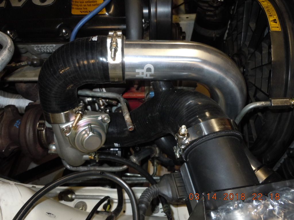
As promised, the long awaited do88 3" pipes and the associated reinforced hoses for high pressure boost! The drivers/intake "cold side" charge pipe:


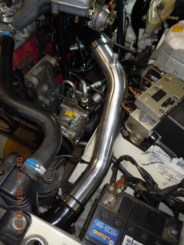
To gain some clearance beneath the intake for the IAC system (yet to come) I opted for the "cobra head" 90* hose from the charge pipe to the throttle body. Here a couple views... a nice piece:


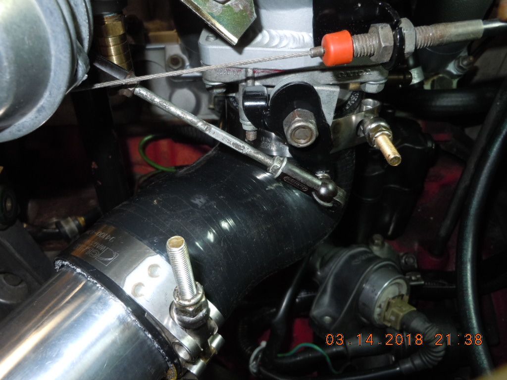
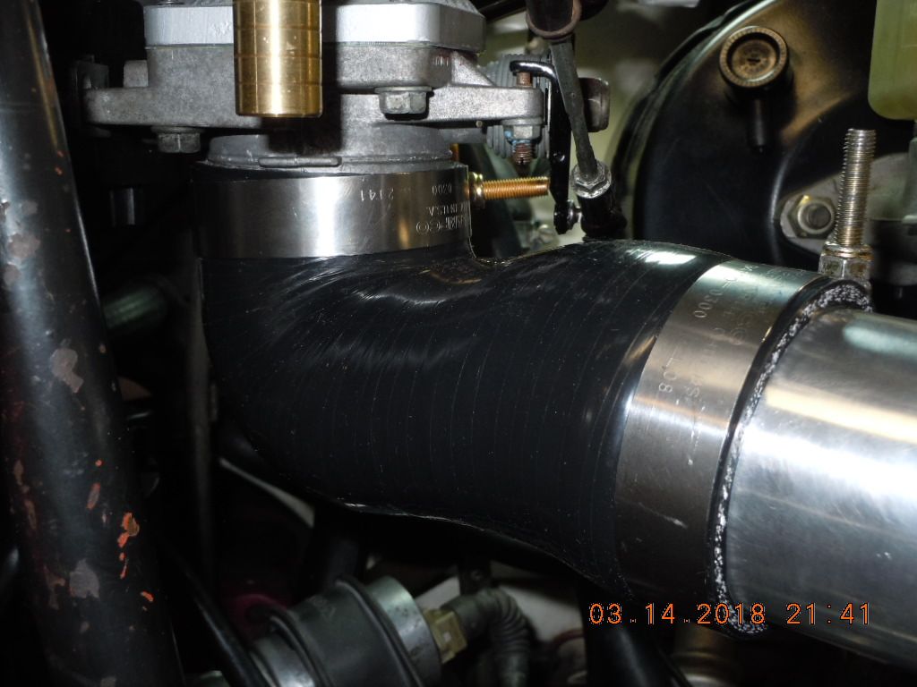
CLAMPCO T-bolt band clamps all around on the intake side; of course they require a bunch of different diameters. I was fortunate to find an eBay vendor that sold various diameters by the piece.

Jumping to the HOT side charge pipe:


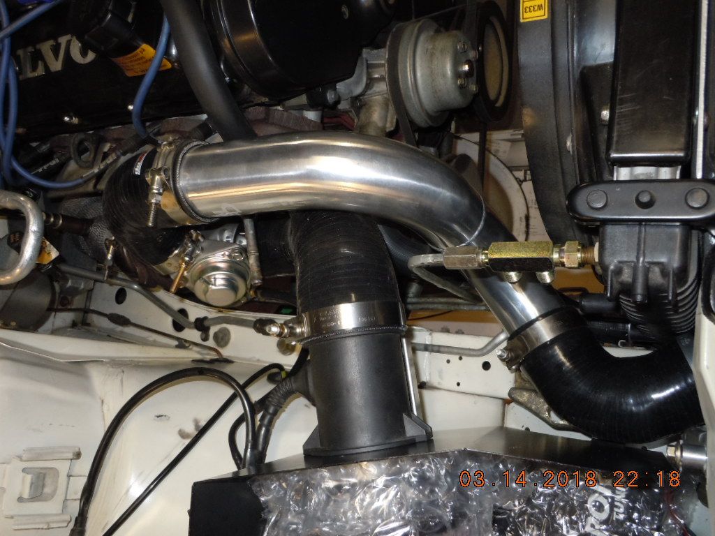
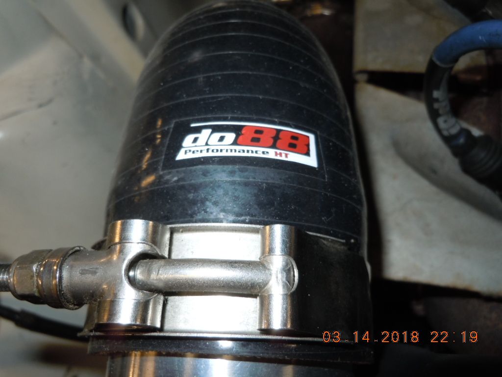
There was just one sticky spot..... landing the hot side pipe to the do88 big intercooler. As you can see, on the exhaust side of the car, there simply isn't room for a CLAMPCO T-bolt band clamp with T-bolt oriented vertical. My initial solution is this, back to back ABA Sweden hose clamps synched up tight:


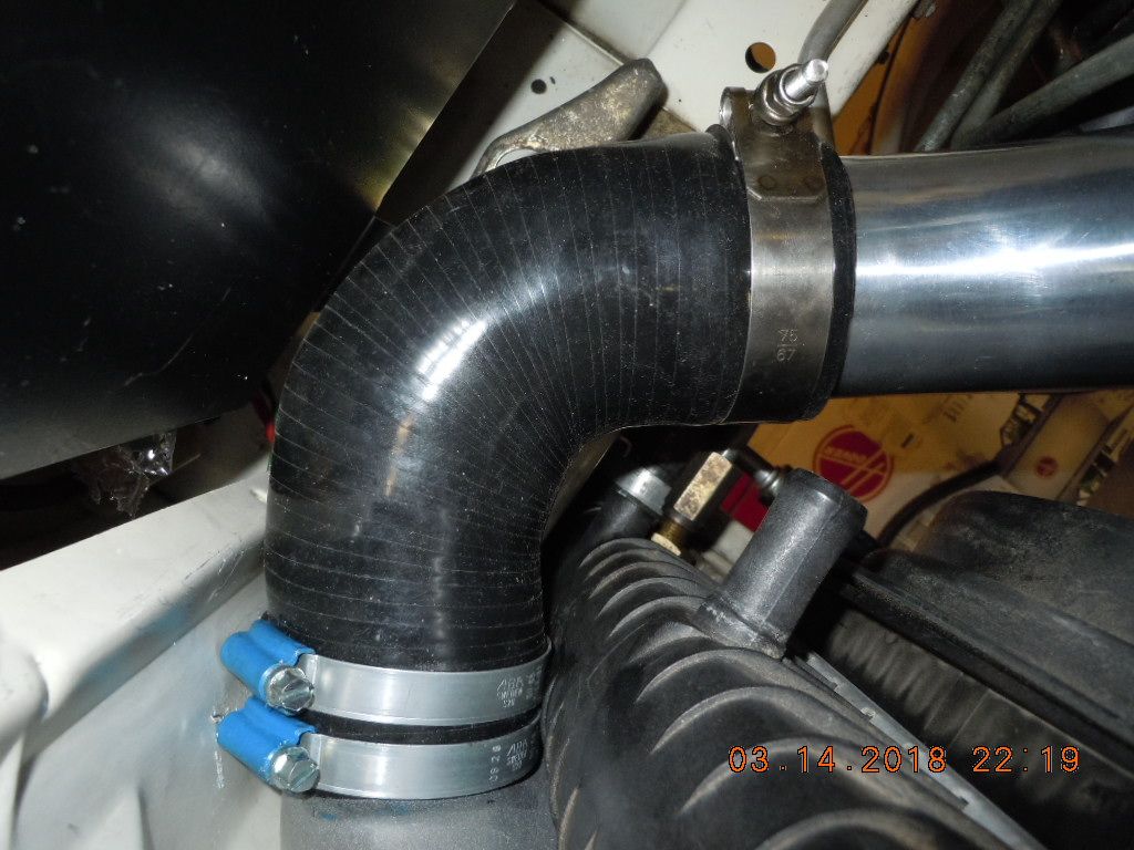
I'll flip those on the final install so they nest tightly together. If my ~18 or so PSI causes this connection to blow off, I'll have to drill an access hole in my front core support (and remove a headlight to access) and then use theCLAMPCO T-bolt clamp I have, installed horizontally at 12 o'clock. But no more sheet metal surgery at this time..... will use this method until the wet testing begins and either confirms function or fails.

I strongly recommend this do88 FMIC and the associated "big pipes" kit. From what I read, this is simply one of the very best improvements that a street driven turbocharged engine can receive.... right there with a true 3" exhaust system.
 
LH2.4 IAC solutions

Next installment. Since my DD still employs LH2.4, I wanted to retain the stock IAC function and benefits.

However with use of the B21F intake (EFI converted), there were no factory provisions for the IAC port; neither does the single post support for the B21F intake have the mounting positions for the IAC valve to bolt onto. The original B230F intake support bracket offers clamping positions for a ground and also power cable.

Well, Nathan's modified B21EFI intake did have a provision to add an IAC port.... he TIG'd a bung on the bottom forward of the TB with female pipe threads. Fortunately I had a brass hose barb that was the correct male NPT size and hose barb of sufficient size such that a lathe created a duplicate for the B230F IAC hose connection (which turns out to be 16mm). Having the target, I just needed a method for relocating the stock IAC to my new system.

Here is the LH2.4 IAC valve mounted:


With the prodigious space created beneath the B21F intake, I connected my IAC valve and contorted hither and yon, until I settled on the location you see. The delivery port (arrow) was ~ oriented to the target on the intake underside; this saves any engine harness mods with this location. The IAC nicely will clear that back of the alternator for any service thereabouts.

I simply transfer punched the center holes to the ancient support post, and step drilled up to the 6mm (1/4") clearance hole; amazingly my cordless drill fit these confines! A couple of long 6mm SHCS were repurposed from my Swedish car stash to provide attachment. Both the original cables which were affixed to the B230F goofy angled intake support also found new homes. So far so good.... what about hoses?


The IAC connection ports require a 22mm hose.... and then they reduce down to 16mm; both the supply and delivery hoses are sized this way. Fortunately, I found a couple "turbo service" 4 ply reducing couplings on fleaBay. The smaller hose is equivalent to 5/8", and I sourced some marine service water heater hoses which were rated for 200 PSI for the top section to mate to the intake. More searching located these Dorman 5/8" heater hose couplers, complete with barbs for hose retention. ABA Sweden clamps were all that remained to finish this delivery hose system.


Well that left the supply side to the IAC valve. My do88.se "big pipes" had a substantial male nipple on top of the cool side pipe, but the routing required a significant corkscrew to attach to the IAC inlet. Volvo solved that issue.... I purchased one of the OE Swedish hoses which connected the original IAC to the B230F intake hose barb (hose looks like a squished "C"). This already had the nice U-turn section of the 16mm hose, which helped with clean packaging. With my other 22mm to 16mm reducer coupling, and removal of the second half of the U-turn (the 22mm end), I was in business:


I'm pleased with how it turned out. Several other B21F intake converts have recorded issues with getting their IAC functional.... but I can confirm there are no packaging restrictions to getting it installed with the OE harness. None of my hose solutions are rubbing adjacent systems (I was concerned about the cobra head TB hose, but it clears nicely).

With the IAC sorted, I finalized the complete cold side pipe & hoses and torqued all connections with the CLAMPCO T-bolts. The only things remaining for me on the intake side of this engine is to solder an extension wire on my AC compressor clutch, install the alternator, route new & longer evaporative hoses to the charcoal canister, purchase a new brake master (servo) hose, and lastly install the discrete hoses from the B21 intake to all the devices which need connection to the plenum. Then I can jump back to the exhaust side and begin installing my "extra oil cooler" for the AW71. Step by step........
 
I'll bet you are. I dig the little reducing hoses. Wish I had stock in ABA...

I don't get the lack of original IAC port on the manifold. I wonder if it got wiped out when Nathan put on the large TB flange.

I believe you are correct about Nathan's mods. He did upsize for the large TB mounting, and if I recall there is a port TIG'd closed directly beneath the LH2.4 TPS. Probably the K-Jet connection for the original IAC, if it had one. I have very little knowledge of K-Jet, and no desire for any!
 
first fit check, non-FOG E-codes & corners

My 92 was born with the less than appealing looking FOG front end. I never really cared for that "wall of glass" across the nose, and pulled the trigger to convert to the more modern looking non-FOG style E-codes, as a part of the last hurrah.

Arjan over in the Netherlands hooked me up...... after receipt, I disassembled these BOSCH light housings and freed up/lubricated all the adjusters. I've just received a set of H4 Osram Super lamps from Europa, and they'll be going into service.

Couldn't take the suspense, and bolted them in last night to see how it will look:


I like it. Apparently there was never a factory eggcrate grille on the 940s with this style headlight. One can "cut and paste" a bit and created a non-FOG eggcrate grille. I'm not holding this job up any longer, as I need this machine back in service NLT end of June 2018. I did learn last night that the black plastic valence which sits atop the grille must match the headlamp style. With all my parts hoarded, I didn't realize this piece was necessary. Not a big deal, there are a pair of late 90's non-FOG 940s in the local Pullapart.

Checking my electrical schematic, it seems the factory lighting relay is in the dash with the fuse & relay cluster. If I want 100% of the lumens possible, I'll have to upgrade to front core support relays so I can run batt/alt. voltage direct to those H4s. Also not a huge deal.... got to study the harness a bit and see if I can complete with minimal wiring revisions. Real E-codes, to be continued.......
 
I just built a non fog eggcrate grill for my gf's 92 740 and installed it. Used a fog light eggcrate center, and non fog surround put together. If you do this, know that you'll need a die grinder to complete it. The center doesn't fit perfectly into the surround, requiring a little shaving, not seen when assembled. Also none of the holes for the pins to hold the pieces together line up, so I drilled new holes in the surround.

Getting it onto the car required hogging out the upper tabs some as the tabs are closer toward the center on the fog light front, of course. It was tight but I got it on.
 
FWIW - when I put separate relays on mine, I simply put a female spade term on the 12V+ wire for each bulb/filament -- and used that to 'trigger' the relays. Used 10 gauge for hot and ground on the all the relay wiring -- and put all the hot side through a 40A fuse under the hood. 0.00V drop on the DVM between power source and bulb at idle for full lumen potential. Doesn't upset the 'light's out' indicator -- and virtually no current now through the factory switches/wiring.
 
The factory 9 setup has a single headlamp relay in the center fuse/relay block, so it's not as archaic as the 2 series setup. It does however run ~14ga wiring as a homerun to all 4 of the headlamp circuits.... with the associated voltage drop. I'll measure what I've got at the H4 connector before I go to the trouble of short run larger gauge wiring.

I put such relays in my 70 Chevelle (a true antique) and the increase in lighting was significant.
 
Extra oil cooler for the AW71

After prodigious delays (work & wife related) I finally got a Saturday to try and push this project closer to the finish line. I arrived at the point where I can't reassemble the front end (lights, bumpers et al) without finishing the extra cooler. Here we go.

After careful consideration I decided to use the existing bumper support-shock M10 fasteners (unused bolt threads) to anchor my custom SETRAB cooler mount. A piece of 1/8" x 1.5" cold rolled steel lends itself nicely to fab the mount. Here you see end of the vertical plates that I carefully fitted to match the hole centers:


You want the oil cooler parallel to the AC condenser for flow reasons. Here I confirmed the cross bar was oriented square to the fins. You cannot slide adjust (rotation and elevation) unless you have some compression against each vertical. Don't cut it too short!


Using a technique learned from old Dad, I "snuck up on" the length to just barely fit between the vertical plates. I decided to elevate the horizontal plate for (1) wrench clearance on the attachment locknuts and (2) so the plate was directly in front of a condenser tube.... allowing the air to flow cleanly on each side thru the fins.

Next I clamped SETRAB cooler to get the weight on the cross bar to confirm the elevation prior to MIG welding. I also needed to confirm hose lengths thru the custom holes I put into the radiator core support.... and then locate L-R to use all of the hose length & finally drill the attachment thru holes into the plate:


Here we are post welding & painting. I have the SETRAB oil cooler bolted in with the ancient hardware kit that came with my 240 trans cooler.


The 9 series, and probably the 7 series as well do not have factory holes for the extra oil cooler hose passage. There was a slot near the top of the core support which I repurposed for a grommet hole; the other hose hole was drilled with my 21mm carbide metal hole saw. Here are a couple views of the newly created holes for the oil hoses:


Since I purchased the 21mm hole saw for the hoses, I decided to use it to resolve my do88 hot side hose connection (previously I could only fit ABA Sweden screw clamps); with some fit checks I realized that I could get the CLAMPCO T-band clamp to work if I had an access hole. If you look near the bottom of this last pic you can see the proper clamp now employed, which I can tighten from the headlight area. The cool factory junction block is shown and the OE Setrab oil cooler hoses.


Prior to calling this cooler "good", I've got to add trans oil to fill the additional volume. I plan to simply remove both hoses at the swivels, pour the oil in one until I see it return in the other. GLAD to have this done as now I can install E-codes as well as the front bumper.

Getting closer to twisting that key........
 
Last edited:
The dented fender leaves.... and SAAB temp switch arrives

ever closer to the finish line.....

Never mentioned it in this thread, but when I bought this 940 back in 2011, the PO told me his daughter had a close encounter with a mailbox. It took me awhile to find it, but sure enough she put slight crease in the pass fender right near the pin striping. Either someone did an expert job touching it up OR the original paint somehow hung thru the mailbox encounter.... unknown. What I do know is now I'm planning to get the entire front clip painted to match the doors back, plus the roof which is a mess in the sunroof area. It already has had both rear quarters and the rear deck lid & spoiler painted, and the doors look fine on both sides. This entire car was repainted at some point in it's life as my Polar White doesn't match OE colors, mine is actually a bit darker.

With the approaching paint job I remembered the almost hidden crease in the fender; then I saw a Polar White 94 model with a near perfect pass. fender at the ATL North Pullapart, and thought since this is really the last hurrah, might as well get it right.

$43 and 45 mins of labor to extract, and here we are:


the last 6 inches of the fender right at the door junction is where the well hidden crease was located. Now the 2 tone pin striping gives away the fender replacement, and the last worst scar on the car is gone.


Also, both fender "doglegs" now have the hideous VOLVO badge removed.... and they will be fitted with the later FWD side marker turning lights which are tied into the front turn signals. Got a kit with wiring from a eBay seller, and then noticed one of the HELLA side markers had the retention clip broken off :grrr: so an eBAY replacement was sourced. I'm going to prewire but just leave the lights off until after the paint is complete; they simply plug into the harness and snap into the fender.

Next upgrade - an additional e-fan control temp switch. The backstory on this is fairly old...... I was having a long running email conversation with StealthFTi about his belief that the LH2.4 engine management ran the red blocks far higher temp than the old school days, and he attributed the accelerated block wear (belling) to these higher operational temps. Related, there is an old thread on TB by folks converting 2 series cars to the later e-fans, and the most common control for these conversions was by use the SAAB top coolant hose "TEE" and a Wahler temp switch for the e-fan control. SAAB used that switch to turn off the AC when coolant temps got too high for their 16V 2.0L engine; the hose connections are perfect size for the red block suction hose.

That said, I sourced a gently used SAAB tee, bought a Wahler 82*C (off at 78*C) switch, then sectioned the suction hose to install. Complete with brand new ABA clamps, here she is ready for wiring:


The control is simple: the OEM relay used for HI and LOW speed fan operation needs a ground input to enable either speed (the ECU and AC condenser hi/low pressure switches provide the signal for these grounds). All I have to do with the new 82*C coolant temp switch (normally open) is land one terminal to ground, the other tied to the low speed input from the ECU; I am NOT removing the original control, just adding a lower temp input for ground. One possible downside of this change is that when cranking of the hot engine the fan might operate putting more load on the alternator at startup. Once running I'll observe the behavior and we'll go from there.
 
Last edited:
As always, nice work DT! Particularly like the mount for the cooler. On your temp control possible worry about the fan adding load during starting -- on my A/C to fan control, I ran the wires inside through a switch in the console. I can now kill the fan completely (as far as A/C controlling it) when I'm under cruise on the super slab. You might be able to do something like that to assure it's off during start up.
 
Project is coming along nicely!

I don't suppose the hood was on that car?

Thank you sir...... nope, that hood was purchased from Wren several years back. Actually still painted in Polar White, when you compare that color to the rest of my car (minus pass. fender) you can see how much darker the repaint actually is.

TONIGHT - coolant and oil change..... the key finger and thumb are itching.
 
Sorry, I meant was the hood still available on the junkyard car you pulled the fender from? If so, which yard was it?
 
Ever closer to back on the road.....

Well it's been a good while since an update.... vacation along with wife's honey-do list work slowing things up a bit, but finally completed some jobs today.

For the first time since April 2017, the car is back on 4 wheels:


All of the rear suspension "torque points" have been waiting for the car to sit on the springs at normal ride height. With all these connections just snugged, I rolled the car forward and backward in my 2 car long basement shop..... this to get everything "familiar with each other" before again elevating the car rear back to ramps for torque application.

Since the rubber suspension bushings torsion as the suspension travels, one must NOT torque them until total weight is back fully on springs & dampers. Once in that "normal ride height condition" the bolted connections are torqued so that the torsion as the suspension articulates is +/- the same amount of torsional strain; that is to say each rubber bushing is neutral at normal ride height. If you make the mistake of torquing these points with the suspension at full droop, you will over strain these bushings resulting in failure. I retained the original VOLVO rubber bushings at the 4 points in the dog bones; Hopefully the added torque doesn't destroy these....and I won't ever run poly joints. We shall see how they do.

For 7/9 Posterity, the front thru bolt on the damper/sway bar (along with pan hard bar) torque at 63 lb.ft, the small rear sway bar flat head bolt is at 35 lb.ft, and the dog bone torque arms which control the rear end reactions are torqued at 103 lb.ft, all 4 points.

Here you can see the various torque points:


Here a picture of the "progressive rate" rear spring, loaded. Note the 4.10 ratio tag on the axle..... looking forward to that +10% torque to the tires!


One of the longterm annoyances for me has been the TME exhaust.... the CAT back 2.5" stainless system. I've always loved the exhaust note.... I think TME nailed that part. The issue I've always had with it was when attached to the pipe exiting the CAT, the rear tip of the muffler was never horizontal, but pointing down toward the road. With the experience TME has in making exhaust, they can't have screwed this up as found. While the guy who sold me this used insisted it was for the 7/9 cars, I wonder if he was given the wrong front pipe (axle forward). Regardless, with the last hurrah it is time to fix this properly.

I elevated one of the rear hangers to level the muffler L-R with the bumper, and customized the front of axle U-clamp with extensions, so that the muffler tip is level to the road as it passes under the bumper:


Of course, the remedy for the muffler created more work at the CAT back area. What I've done is purchased a couple pieces of stainless 2.5" pipe, and will buy a mandrel bend that I plan to section up and then butt weld it all together. Looks like the old man will be learning how to MIG stainless...... skills that will be needed in my future 242 Whiteblock build.

Here's the section that will be modified for a nice smooth flow to that IPD tip:

 
Last edited:
Back
Top