The story continues from post #82
Update 1-6-2020 (A sad covid story)
A while ago it was decided to make a flywheel swap along with pressure plate and clutch disk. Some fractured flywheel pictures and the fact that on 240 this huge rotating mass is next to driver's legs lead to that decision. Of course it should be upgraded not only in terms of strength but clamping force as well despite the car had no clutch slip problems up to now and no signs of anything dangerous since everything was balanced from the start.
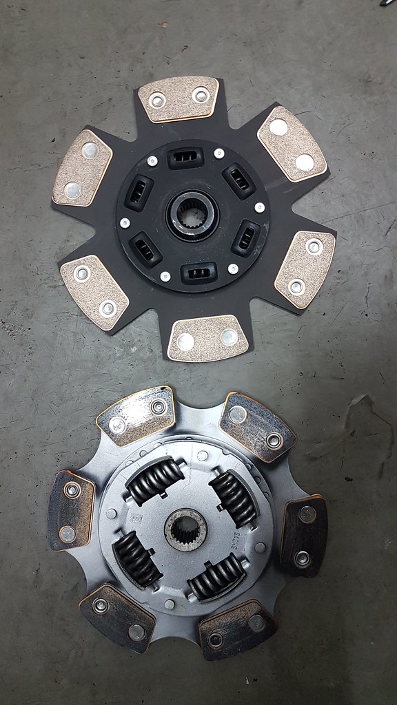
After lots of search i went for Bakaxel's option which accepts Sachs 618, Sachs 765, Sachs 707 and ACT [It has the center to be able to run with 184mm (7.25 ") clutch (eg Tilton or ACE Racing clutch)] pressure plates on a single flywheel ! Along with the flywheel a 6 puck sprung clutch disk was chosen which features 6 springs and a 765 pressure plate. This setup would provide more strength than probably needed, as well as flexibility for any other setups. As a side note, the build quality and the accuracy of the parts are amazing, exactly as advertized. Jonas on bakaxel is a very smart man and knows what he is doing providing very good advice.
So the party started by dropping the gearbox out of the car, making all the measurements LOTS of times, since there are stories flying around for bad installations causing problems.

The old setup was in a surprisingly good condition despite the dyno sessions !! No clutch disk play or slip !!


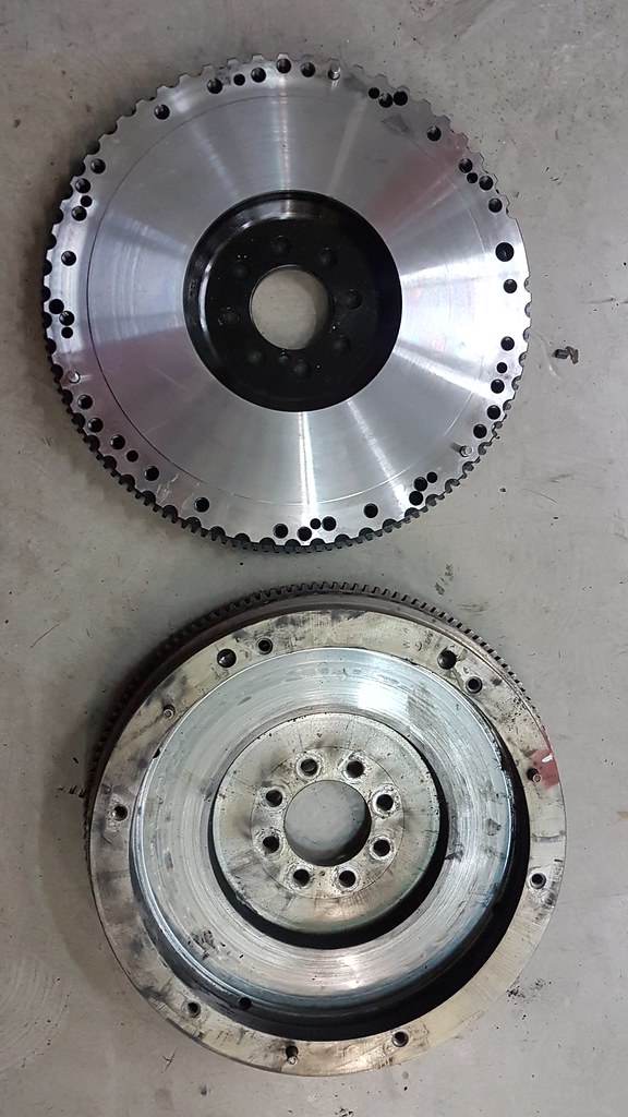


Huge weight difference for the flywheel. However the pressure plate and clutch disk for 765 are much larger, so the weight difference is reduced to a total of about 5 kgr.


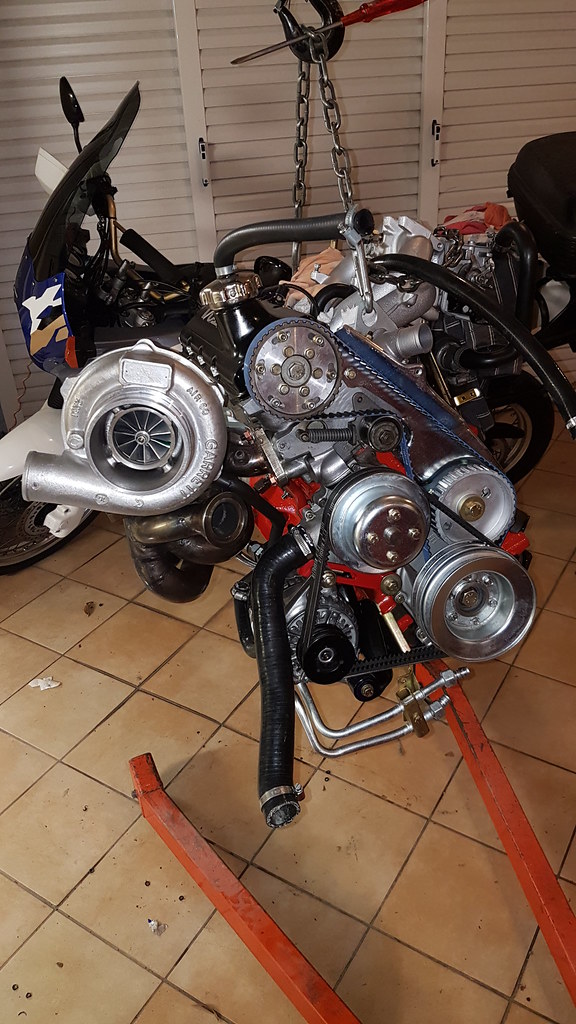
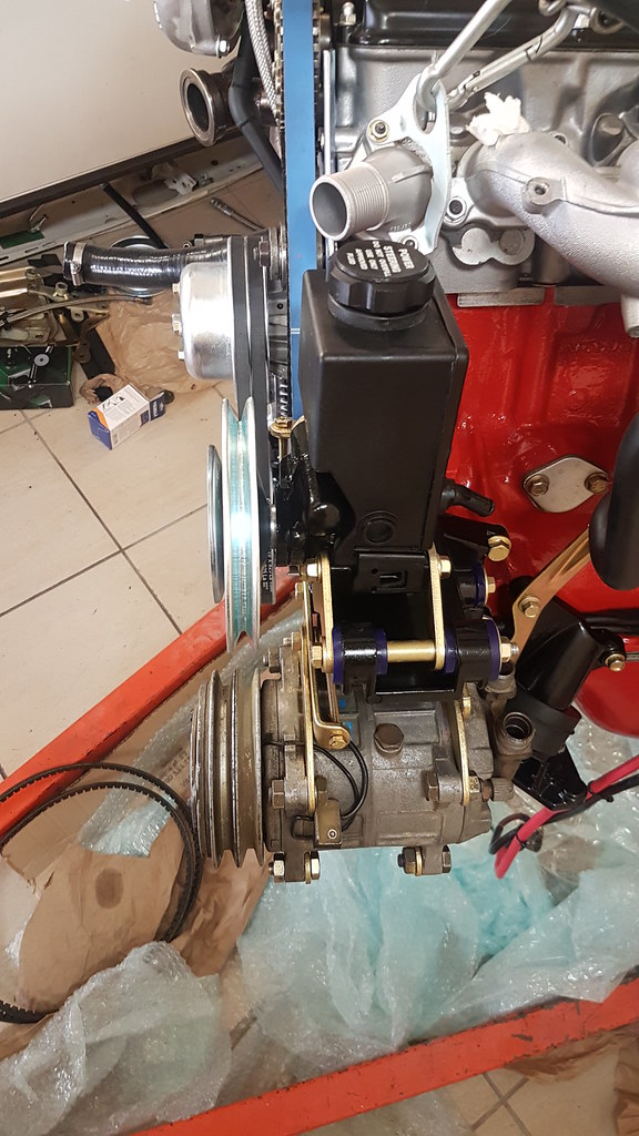
The new setup - looks nice .. bigger & stronger :
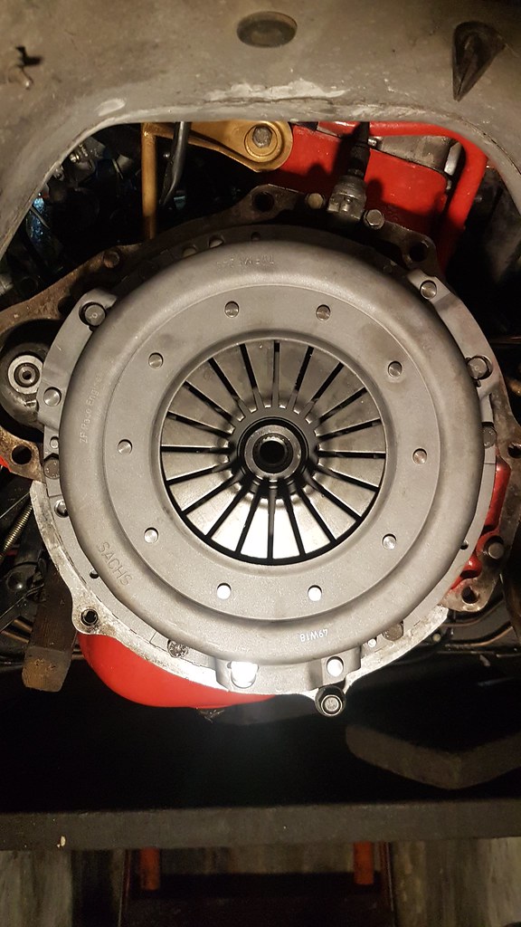
Perfect tolerances from Jonas (bakaxel) .. fits as it should to the millimeter. However for checking everything the engine was rotated to see if the flywheel has any kind of grinding action. Everything perfect !

After all that, the gearbox was test fitted 3-4 times, till the sweet spot for the clutch pedal was found (moved the pivot ball to adjust the clutch engagement as good as possible). During that procedure every measurement was double checked, including the clutch disk center clearance from the gearbox's tube that the clutch bearing slides on. Jonas had warned that this could be a point of interference, so it was triple checked. Also it would leave a mark on the disk's center surface in any weird situation.
As for the new setup, for sure the left foot will do much more work, but frankly it is not as huge difference as was expected. By adjusting the pivot ball (ended up adding 3 shims) the left foot work was definitely reduced. When everything was good the disengagement was tested a bit more, moving the car back and forth after turning the gearbox's output shaft by hand to see that it actually works as it should and checked that there are no grinding marks or noises.
Everything was ready to fire the car for new adventures ! Test starting the engine .. nope, wouldn't start ! After a bit of a search was found that the wideband sensor was unplugged (which also feeds the DTA ecu) so this is why it would not start. But that was a minor problem. The starter motor had a hard time turning the engine. As a note a new battery was installed 3-4 days before the swap, so this was the first suspect ! Voltage was right, but the problem was the same. Under the car for one more time checking that everything disengages properly. Moved it around with clutch fully pressed and in neutral, everything was right. Dumped the clutch the car would stop immediately. Back to the battery then. Used an amp clamp to measure the starting current, north of 300 Amps which sounded good. Having tested everything, the next suspect was the starter motor. The flywheel gears could not be wrong, since the mesh would not be possible and would not turn at all, so this was ruled out as well.
So the next idea was the timing. If the sparks were wrong, due to some difference to flywheel gap, it would prevent the engine from starting. Disconnected the ecu and found out that the starter motor still had hard times. But the flywheel timing gap position was measured before installing it, and was exactly the same.
Connected everything back, and decided to insist on the starter till it starts the engine, and so it happened. After 4-5 seconds the engine was alive. No weird sounds, no nothing. The rpm were kept at 1500 for a while since the idle motor is not yet programmed into stepping in when needed. Watched the oil pressure, egt etc for a few seconds, everything perfect. After 10-15 seconds the gas pedal was released, the engine automatically turned off.
A second try to start the engine, it fired up much faster, but same starter motor difficulty, kept the rpm at the same range for 10 seconds, let the gas, turned off by itself again. Only weird sign was the oil catch can had some thin white smoke spitting out, but this was considered normal because it was raining for 3 days, and it usually does that since the oil gets moist by the atmosphere.
One more try for 5 seconds, lots of smoke from the catch can, the turbine sounded spooling hard i stopped the engine. After 4-5 minutes the spark plugs were removed to check if the engine turns ... and that was it. The engine was dead. No possibility to turn it by hand. 5th gear on the gearbox, pushed the car, dumped the clutch, nothing. The engine was stuck. Given that all indications of pressures were correct during all these tries, and that an engine can run without oil for at least 20 minutes before getting stuck ... the reason was a real mystery...
The next thing that happened was this:


So what stopped the engine from turning ? Here is the reason:
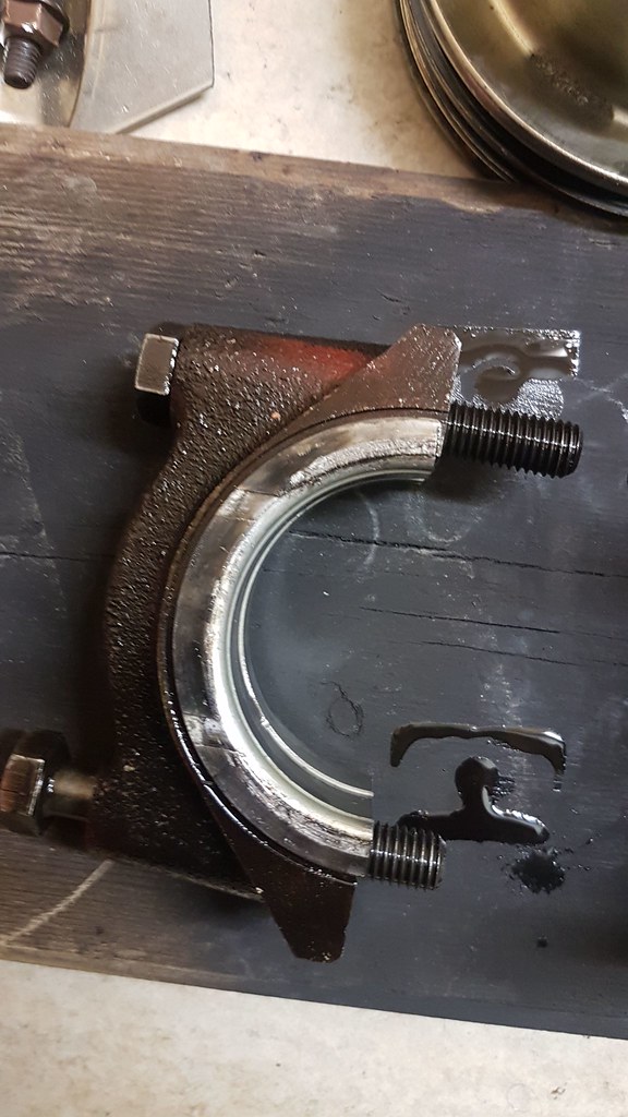
This is the thrust bearing of the B21 located at position 5 (close to the flywheel). If you look closely its surface is grinded. The material that is missing was stuck on the crankshaft. But what was the cause ?
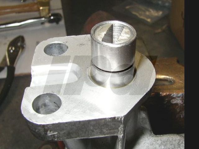
Here it is:

The story behind this retro turbo's gearbox spigot shaft centering bearing was pretty simple as it turned out. On the dog dish flywheel this adapter fitted perfectly in the center hole of the heavy part. BUT the new flywheel had a center hole 5mm less than the old one. So i took the adapter to the machine shop to reduce its "mushroom head" diameter for it to fit to the new flywheel. I asked the machinist if we should do a tenth of a millimeter more so it fits easily by hand as it was in the past and not a snug fit. He insisted on having it to be hammered to its place. And this 1/10 of a millimeter ruined the engine ! As it was proved, despite being hammered, it went in slightly angled in because the aluminum made a notch on a single spot from the hammer (maybe less than 0.5 mm from side to side height difference), but it was enough to let the spigot shaft go in the bearing, while at the same time when the gearbox was bolted not show anything weird but push the crankshaft towards the front. And as the crankshaft was pushed, the main thrust bearing melted after a while since it was oiled, and when the engine started and burned the oil at the spot.. causing havoc ! Of course somebody could think that the spigot shaft front "lip" pushed the adapter's bearing having the same result ... but no, this was checked as well. It was the angle of the adapter !
So since the engine was out of the car, it was time to make some improvements:
- Replaced the old water pump hose: This particular hose is different to the B230 sold by STSmachining which will not fit. Also this turbo hose pn 1332613 (1306162) is made out unobtanium and is not available anymore. So i got my chances and bought one for non turbo B21/23 hose pn 1219654. Since i have a different exhaust manifold and turbo location, it fits on the block. It has a minor difference on the part of the hose being more angled (flywheel side), but this should not be a problem.
The old turbo version hose:


The non turbo version hose:


- Refreshed the block paint with some Viking blood

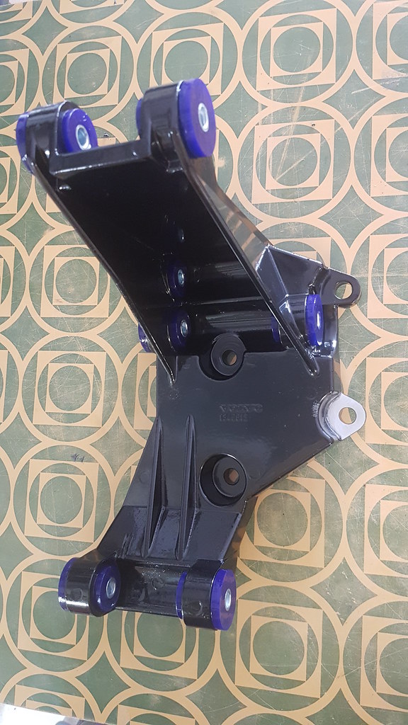
- Powder coated some parts, color is not spot on, but as we say in Greece it is for the "bad eye", some defects protect you from being jinxed.
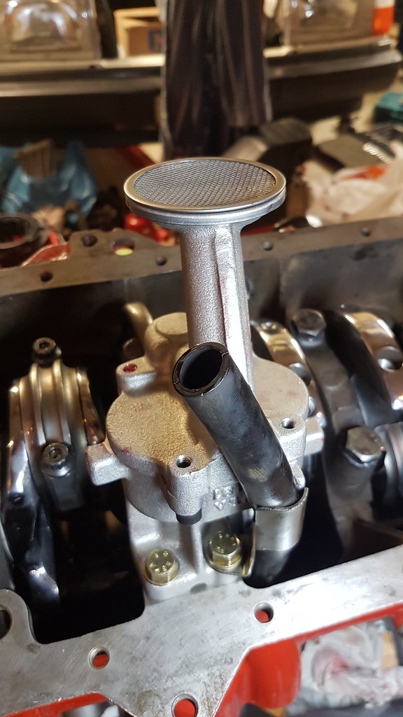
- Replaced oil pump with a Melling M181 high volume. As it is not clear that the Melling pump had the tall gears inside i ordered one, and measured it (thanks Gary). Also i replaced the stock Melling spring with my custom made which is 70% harder. Also as a note Volvo has produced some pumps with the part number of the Penta (high geared) pumps, BUT they actually are NOT high geared !! I was told that this would be fixed since they started the production of the correct ones. But in any case they don't look they have the same good quality casting as in the past.
Tall vs short oil pump gear.


Hard spring used:

Stock melling spring same displacement:

- Added an 1.3mm thick stainless steel oil pump hose o ring guard for not popping out under pressure (thanks again Gary for the idea and the photo) and an oil pump reinforcing ring similar to ipd's but custom made.

- Noticed a weird issue found here https://turbobricks.com/forums/showthread.php?t=354036 which i found no reason happening. Btw part number of the shaft is 463365.
- Drilled and tapped an -10AN to 3/4 oil return fitting on the block. Drill and tap kit from Amazon was surprisingly cheap !


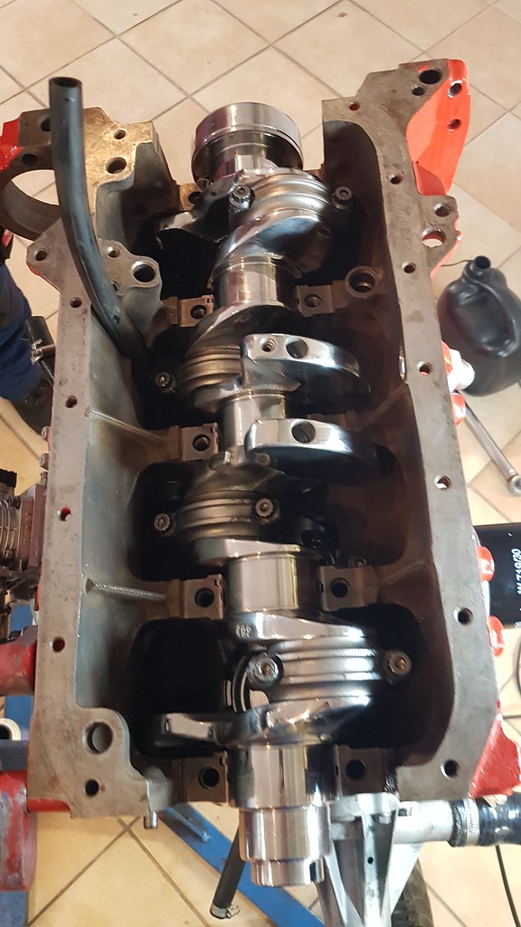
- Polished and balanced the crankshaft - flywheel - pressure plate - pulley

- Added a long breather box return hose and its holder from the donor skinny rod B230
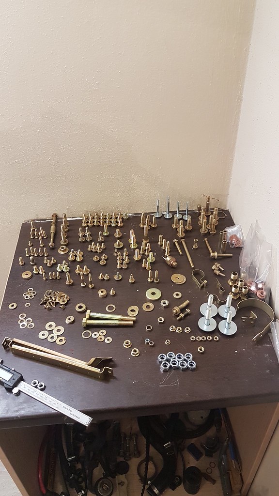
- Satisfied my OCD by restoring the gold color of the bolts and several other parts of the engine
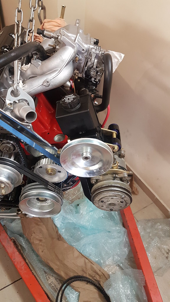
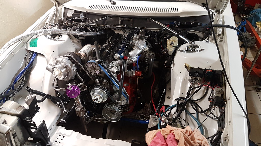
Here are some photos putting the engine together ... at last !!


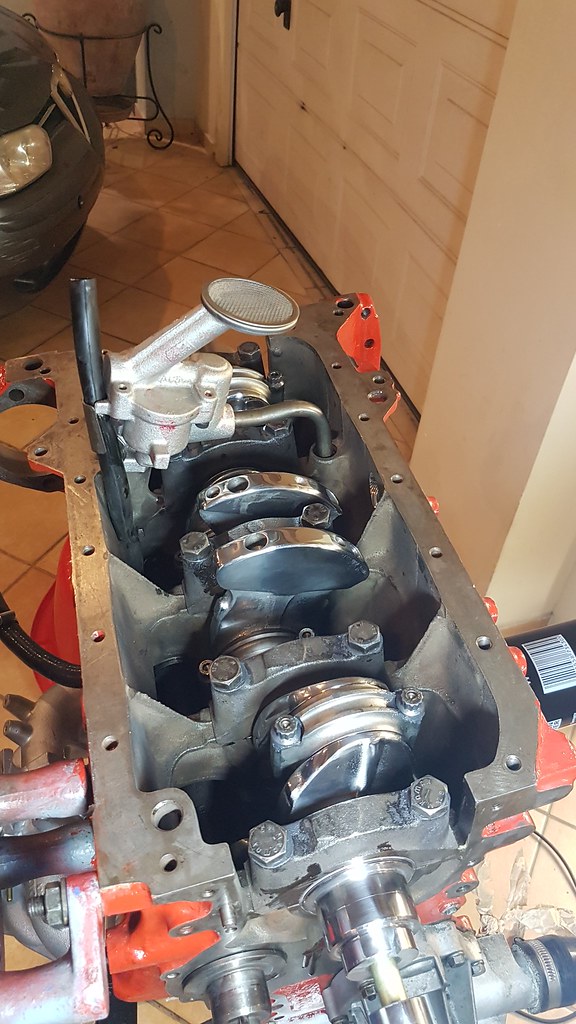


Two oil pan gaskets needed due to my custom designed pan plate (one on the top of it and one on top of the oil pan). Due to the difficulty using liquid gasket in 4 places (each side of each gasket) while aligning the block holes it was installed step by step.
 Some more upgrades/improvements:
- Upgraded timing belt to a kevlar Gates T032RB

- Upgraded turbo return line to -10 AN PTFE braided setup: The old rubber line was cracked and brittle. Lucky to have found on time..

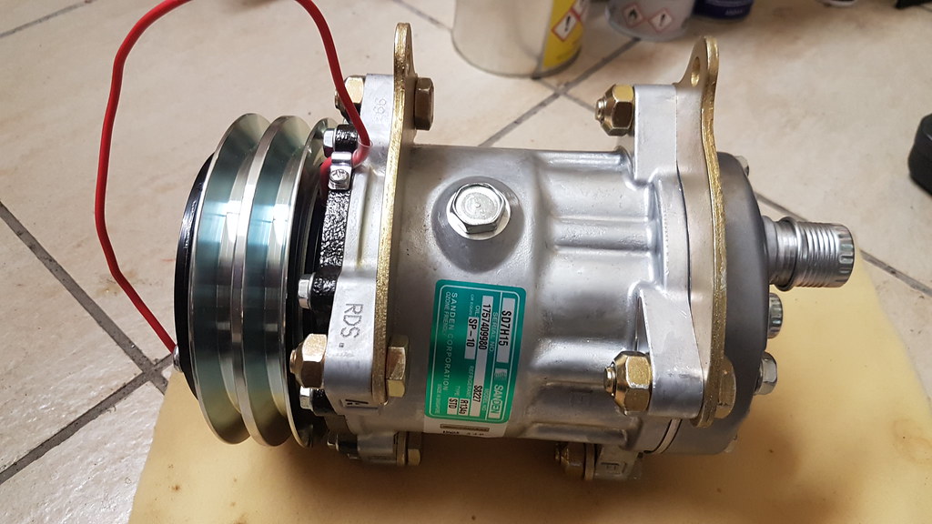
- Changed starter motor to a newer style high geared one. Lighter smaller prettier setup !

- Added more grounds connecting the 100A Denso alternator to the block. The standard cable was looking exhausted so 2 new thicker cables were added from the 8mm bolt on the rear of the alternator to its 12mm bracket bolt, plus a braided flat cable (same type as the one on the cylinder head to firewall) from the second case grounding stud to the front tensioner bushing bolt. This should be an overkill but still, it is better to be on the safe side.
- Changed the turbo circulator temp switch to an ALFA light switch 60537203 (7.4079 Facet) which is turns on above 45*C. Especially during winter when the car was turned off, when the circulator operated, the water temp dropped easily below the 67*C turn off point of the old switch, so the turbo wouldn't have much time to cool down by the circulator. This switch checks only if the engine is hot so not to operate the circulator when the key is turned on and off for no reason.
Continued at post #112--->LINK<---

 Much effort was put to address any problems and improve any "weak" spots that could be found on this build. Hopefully everything was covered.


")


