• Hello Guest, welcome to the initial stages of our new platform!
    You can find some additional information about where we are in the process of migrating the board and setting up our new software here

    Thank you for being a part of our community!

Fitted daughter board, now it won't start!

Arewethereyet

New member
Joined
Jan 8, 2017
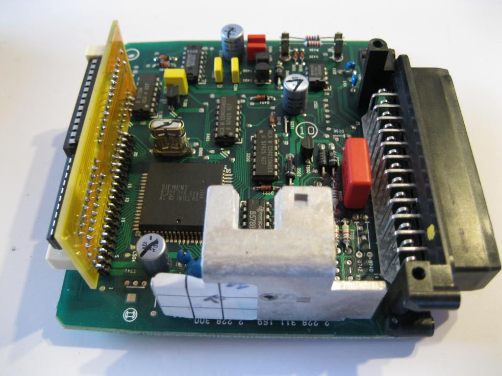
Hi all, well I've assembled the daughter board from ClassicSwede but now have no spark. Ive belled out the tracks from the header pins to the cpu pins snd all are fine except one which is the first from the right when looking down onto the cicuit board from the top, that doesn't link directly to the cpu terminals (if that makes sense)
I've belled between capacitors, resistor, the via holes and all seem fine.
Where does that short track mentioned above go to, as I cant work it out. Would that cause a no start whether the jumper in place or not?
 
This is why I decided to go with the Yoshifab daughter board that is already assembled. I was concerned I would get something wrong building it up.

Hopefully you get it sorted.
 
its nice to know im not the only one experiencing this problem. i just went through the same problem.

I have a excellent workstation at the university and a heated solder extraction gun. im actually pretty good with electronic repairs and ive rechecked all my solder points and everything checks but my car wont start with the jumper in either position, or with a chip in it.
 
1. 940 lpt
2. No spark, thats why it wont start
3.Me too
4. Great, if this is what happens then why is there no trouble shooting guide?
 
Sure sounds like the daughter board is offset or flipped around -- can you post a picture of your installed board? (or a plain link to a PBsux picture)
 
Please confirm that pin 1 of your daughter board goes into the EZK pcb trace labelled T741 as shown in this picture, and that there is one empty hole on the EZK pcb at the other end of the daughter board connector (on the left side when the db is facing you). (The original connector on the EZK PCB is 23 pins, with pin 2 blocked as a key, and pins 1 and 23 as a guard trace. The blabla daughter board only connects to the inner 20 of the 23 pins.)
Foto61_zpsc1c5c2e8.jpg
 
Sorry to be the bearer of bad news....

The owner of those build instructions should really update the instructions and post better pictures showing the empty hole on the left side (or should photoshop the existing pictures to "fill" that hole so that the alignment is easier to see).

If it were me, I'd cut all the header pins and then remove the cut pieces one-by-one from both boards. You'll need to find a replacement header but it should be cheap compared to the risk of lifting a trace and damaging a PCB. You want a: 0.1" male right angle single row header, 20 or more pins. They're ~$0.10 each from china in quantities of 50. I don't know if there's a place that has cheap shipping (aka postage stamp) for small quantity low cost parts.
 
i think there are some at work. just still not looking forward to it but i'll make it happen.
thanks for the help i cant wait to put my turbo ezk chipped in my car. i just swapped in a turbo clutch so im extremely giddy.
 
Thanks for the info I have quoted your post on swedespeed and will also stress this in the instructions.

I owe you a pint

Please confirm that pin 1 of your daughter board goes into the EZK pcb trace labelled T741 as shown in this picture, and that there is one empty hole on the EZK pcb at the other end of the daughter board connector (on the left side when the db is facin
g you). (The original connector on the EZK PCB is 23 pins, with pin 2 blocked as a key, and pins 1 and 23 as a guard trace. The blabla daughter board only connects to the inner 20 of the 23 pins.)
Foto61_zpsc1c5c2e8.jpg
 
And me. My board was also one pin over. Got a new 36 pin header from Maplin for ?1.99. Hopefully the tracks of my boards will take another desolder/resolder.
 
Back
Top