BB-Q
(. )( .)
- Joined
- May 30, 2005
- Location
- Costa del Fylde
First off, this is not really my own work. Yes, I made this one and did my pipes with it, but full props must go to Chris Wiita AKA The POI for the original idea and it's execution. I've only done this to help those who seemed a bit confused in a thread in P & S.
This is how I did it and I assume no responsibility for damage caused to people or objects as result of using my methods. Please wear appropriate eye protection too- I've had bits of metal removed from my eyes on several occasions over the years and it is not pleasant.
The reasons for doing this are very simple. That shiny aluminium tube that looks so pretty in your engine bay is not so good at retaining the silicone hose and clamp once boost pressures get much past 12-14psi. So it needs a bit of help. Think of it as a welcome obstruction to preventing the intake air making it's bid for freedom before it goes through the engine. Since the turbo's had to work so hard to cram all that air into your intake it seems a shame to lose it on the way. Another, very good reason is that popping off hoses at full power can over speed your turbo and potentially damage it.
Firstly you'll need two slugs, or billets, of metal about 1 1/2" across- although the size isn't too important as long as it fits inside your I/C pipe. To be honest, the bigger the better- although that could cause other accuracy issues too, so lets not go there! I had to get mine from a machine shop, although I think those of you in America can get the relevant billets from McMasters or somewhere like that.
I don't have any pictures of this part of the process as I didn't know I'd be doing a write up on it at the time, But I'll put this one up so you can see what you are aiming for:

Firstly, if the billets don't have holes in then drill one in the centre of each one. Accuracy is very important here- measure twice drill once. The holes should be of a size that will allow the bolt you have chosen to go into the side of the vice to rotate freely but fairly snugly in the billet.
Once you have your centralised holes you can go to the next step- shaping the formers.
Take a long bolt and put it in a billet, bolting it up tightly. Then put it in a drill. I used a normal electric drill in the vice, but this is not ideal. A properly mounted bench or pillar drill would be far better.
With the drill in the vice (or on your bench or wherever) take your angle grinder and ensure that when it is switched on it is counter rotating to the billet in the drill, otherwise you'll be just synchronising drill and grinder speeds rather than shaping metal.
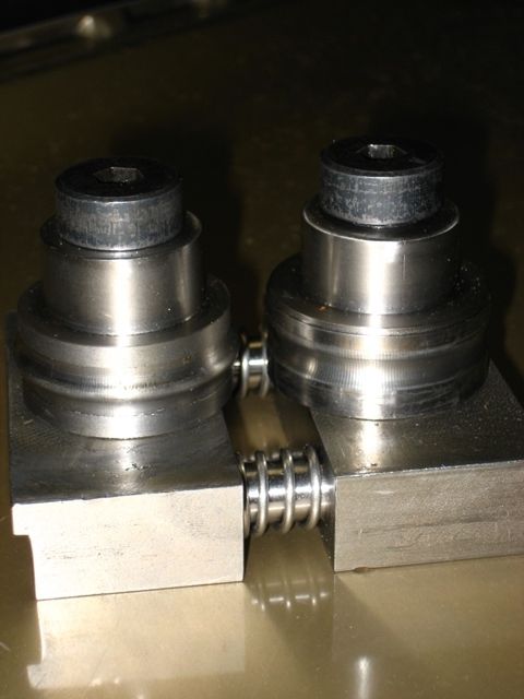
The plan is to form a shape like this:

With a male and female side to the former. From that image I'm going to call the lower former the male and the upper the female. If you look closely at the picture you will notice that the male former's protrusion is much narrower than it's female counterpart opposite. You will also see that the gap is fairly even between them throughout the profile. It is very important that the resulting formers look like this (or better!) to prevent a cutting action when you try to roll a bead. Failure to do this will just ensure that your pipes get shorter with each attempt to roll one.
Right, you've done that bit? Good.
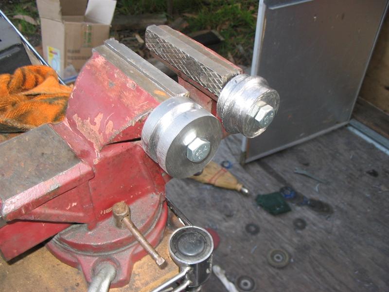
Now drill the relevant holes in your vice to allow you to tap a thread in there. Remember that for an M6 thread, for example, you do not need to drill a 6mm hole!
Also, try to drill into the cast part of the vice as it's much softer. Make sure you position the holes so that the two formers will touch before the vice closes, otherwise you're kinda screwed.
When choosing your tap don't use a cheap and nasty one like I did or it may snap without warning causing you to have to redrill your former and have to drill and tap the case hardened steel jaw on one side. Ask me how I know
Right, you done that bit now? Go get a bit of pipe!
The next bit is really simple as long as you are patient.

Put the pipe into the formers as shown and close the vice until they are just touching the pipe. If you try to make a bead in one pass you will just end up with an unusable triangular profile bit of scrap. It takes 5-10 minutes to make a bead, so take your time.
Start rolling the pipe, ensuring that you feed it into the formers as you're rolling it to prevent any catastrophic warping. Don't worry if it warps slightly- it does not need to be perfrectly round to seal. Also, you can easyily bend it back into shape if it does distort without taking it out of the formers. Difficult to desribe, but easy to do- promise!
After a few passes tighten the vice up a tiny amount. Pretty soon your peice of pipe will start to look like this as a bead starts to form:

Keep going, keep tightening a tiny bit at a time and you'll soon have a bead in your pipe looking something like this:

The profile of your bead will undoubtedly vary from mine as each set of formers is going to be unique. No, it's not pretty, but the only person who'll ever see it is you, so who cares?!
You'll notice too that the bead is not massive- it doesn't need to be. It has increased the diameter of the tube enough to increase the clamp tension significantly as the pressure tries to force the pipe and hiose apart. That is it's job.
After doing this modification I have gone from popping off hoses and anything above 14psi to using 20+psi with no issues at all. Hopefully your results will be as favourable.")
This is how I did it and I assume no responsibility for damage caused to people or objects as result of using my methods. Please wear appropriate eye protection too- I've had bits of metal removed from my eyes on several occasions over the years and it is not pleasant.
The reasons for doing this are very simple. That shiny aluminium tube that looks so pretty in your engine bay is not so good at retaining the silicone hose and clamp once boost pressures get much past 12-14psi. So it needs a bit of help. Think of it as a welcome obstruction to preventing the intake air making it's bid for freedom before it goes through the engine. Since the turbo's had to work so hard to cram all that air into your intake it seems a shame to lose it on the way. Another, very good reason is that popping off hoses at full power can over speed your turbo and potentially damage it.
Firstly you'll need two slugs, or billets, of metal about 1 1/2" across- although the size isn't too important as long as it fits inside your I/C pipe. To be honest, the bigger the better- although that could cause other accuracy issues too, so lets not go there! I had to get mine from a machine shop, although I think those of you in America can get the relevant billets from McMasters or somewhere like that.
I don't have any pictures of this part of the process as I didn't know I'd be doing a write up on it at the time, But I'll put this one up so you can see what you are aiming for:
Firstly, if the billets don't have holes in then drill one in the centre of each one. Accuracy is very important here- measure twice drill once. The holes should be of a size that will allow the bolt you have chosen to go into the side of the vice to rotate freely but fairly snugly in the billet.
Once you have your centralised holes you can go to the next step- shaping the formers.
Take a long bolt and put it in a billet, bolting it up tightly. Then put it in a drill. I used a normal electric drill in the vice, but this is not ideal. A properly mounted bench or pillar drill would be far better.
With the drill in the vice (or on your bench or wherever) take your angle grinder and ensure that when it is switched on it is counter rotating to the billet in the drill, otherwise you'll be just synchronising drill and grinder speeds rather than shaping metal.
The plan is to form a shape like this:
With a male and female side to the former. From that image I'm going to call the lower former the male and the upper the female. If you look closely at the picture you will notice that the male former's protrusion is much narrower than it's female counterpart opposite. You will also see that the gap is fairly even between them throughout the profile. It is very important that the resulting formers look like this (or better!) to prevent a cutting action when you try to roll a bead. Failure to do this will just ensure that your pipes get shorter with each attempt to roll one.
Right, you've done that bit? Good.
Now drill the relevant holes in your vice to allow you to tap a thread in there. Remember that for an M6 thread, for example, you do not need to drill a 6mm hole!
Also, try to drill into the cast part of the vice as it's much softer. Make sure you position the holes so that the two formers will touch before the vice closes, otherwise you're kinda screwed.
When choosing your tap don't use a cheap and nasty one like I did or it may snap without warning causing you to have to redrill your former and have to drill and tap the case hardened steel jaw on one side. Ask me how I know
Right, you done that bit now? Go get a bit of pipe!
The next bit is really simple as long as you are patient.
Put the pipe into the formers as shown and close the vice until they are just touching the pipe. If you try to make a bead in one pass you will just end up with an unusable triangular profile bit of scrap. It takes 5-10 minutes to make a bead, so take your time.
Start rolling the pipe, ensuring that you feed it into the formers as you're rolling it to prevent any catastrophic warping. Don't worry if it warps slightly- it does not need to be perfrectly round to seal. Also, you can easyily bend it back into shape if it does distort without taking it out of the formers. Difficult to desribe, but easy to do- promise!
After a few passes tighten the vice up a tiny amount. Pretty soon your peice of pipe will start to look like this as a bead starts to form:
Keep going, keep tightening a tiny bit at a time and you'll soon have a bead in your pipe looking something like this:
The profile of your bead will undoubtedly vary from mine as each set of formers is going to be unique. No, it's not pretty, but the only person who'll ever see it is you, so who cares?!
You'll notice too that the bead is not massive- it doesn't need to be. It has increased the diameter of the tube enough to increase the clamp tension significantly as the pressure tries to force the pipe and hiose apart. That is it's job.
After doing this modification I have gone from popping off hoses and anything above 14psi to using 20+psi with no issues at all. Hopefully your results will be as favourable.
 . Looks great dude!