• Hello Guest, welcome to the initial stages of our new platform!
    You can find some additional information about where we are in the process of migrating the board and setting up our new software here

    Thank you for being a part of our community!

122 T5 motor swap. Its name is Bluey.

Nice build, that color looks great on an Amazon! Wish I were closer, I'd snatch that b18 drive train and all to build and swap into my Amazon!
 
What are you thinking of doing for the speedo drive?

I have a friend who's an EE and we've talked about converting it to electric drive with the speed controlled by an ABS sensor and a tone ring mounted to the output shaft of the transmission, using the driveshaft bolts. We've already sourced the motor and I've designed the adapter. I've also confirmed that the motor gives a linear speed output with voltage. Then it's just a simple box to convert the pulse input to voltage output, with a calibration button of some kind. Should be cool, I really want to keep the original speedo.
 
I have a friend who's an EE and we've talked about converting it to electric drive with the speed controlled by an ABS sensor and a tone ring mounted to the output shaft of the transmission, using the driveshaft bolts. We've already sourced the motor and I've designed the adapter. I've also confirmed that the motor gives a linear speed output with voltage. Then it's just a simple box to convert the pulse input to voltage output, with a calibration button of some kind. Should be cool, I really want to keep the original speedo.


Are you thinking of driving the speedo shaft with the motor? It might be simpler to take the feedback from the tone ring and control the speedo with a stepper motor. This would be a pretty simple application for an arduino controller. Hardest part would be driving the speedo wheel. I haven't seen what they look like on the inside but a basic o-ring friction belt drive could be simple to implement.
 
I wanted to do a stepper and just direct drive the ribbon drum but that would still leave the odometer non functional. Or do you mean running the stepper at a given RPM? In the end I'm not the EE so I'm leaving that to my buddy. Even if there's some deviations here and there it'll probably be just as accurate as an old worn out speedo system anyway. And I'll be pulling apart the assembly and doing a full grease-it-up restoration to make sure it's as smooth as it can be. I'll actually be using the odometer to calibrate it, and then adjust the speedo drum to match. It is adjustable, only it has to be done with the whole thing disassembled. There's a non-contact magnet drive on one end, and a really light brass clock spring on the other end, which can be tightened or loosened. The odometer is direct gear driven by the cable input.
 
I wanted to do a stepper and just direct drive the ribbon drum but that would still leave the odometer non functional. Or do you mean running the stepper at a given RPM? In the end I'm not the EE so I'm leaving that to my buddy. Even if there's some deviations here and there it'll probably be just as accurate as an old worn out speedo system anyway. And I'll be pulling apart the assembly and doing a full grease-it-up restoration to make sure it's as smooth as it can be. I'll actually be using the odometer to calibrate it, and then adjust the speedo drum to match. It is adjustable, only it has to be done with the whole thing disassembled. There's a non-contact magnet drive on one end, and a really light brass clock spring on the other end, which can be tightened or loosened. The odometer is direct gear driven by the cable input.

Forgot about the odo, that would complicate things. A motor running at speed would kill two birds with one stone.
 
Basically, except ours would be open loop instead of closed, it'll only go out of calibration as things wear or get sticky, and because of that it'll only cost about $20 plus our labor instead of $339. I will tell my friend I can buy one for $339 and see what he says.
 
My friend said we'd have hours and hours of labor in it so if it's one off, I'm better off buying the one you linked! hehe. The one we build would be specific to 122s anyway, not a ton of market.
 
I was waiting to update this thread until I got some actual welding done on the intake and exhaust but my welding buddy has been very busy and I won't get anything done for a few more weeks anyway. Also I've been really unmotivated due to my unemployment. You'd think it'd be the opposite, right? Except everywhere I turn I feel like I need to spend some money to make progress. There are like 3 things I can do without spending money, but it all seems pointless because when I'm done I hit the wall of needing to spend the money. Anyway, it's just a hangup and I've still made some slow progress. Also there are some job prospects on the horizon, we'll see.

First I bolted the pan back on and put the motor back in to verify clearances. So far so good:

122_580.jpg


122_581.jpg


122_582.jpg


Then I used some of this perforated strip material that I had laying around to fixture my turbo flange. It's surprisingly easy to manipulate while being more than rigid enough to hold it where I want it.

122_583.jpg


Up-pipe clearances look good, I'll need a little more than a 45 down here though.

122_584.jpg


Here the turbo hotside is resting about an inch forward of its actual position so I can clear the studs in it, but otherwise its relation to the head is correct.

122_585.jpg


Looks about right

122_586.jpg


And the cold side just hanging in space, rotated about where I want it, should be just about perfect with room to grow into a slightly larger turbo if I ever get the lust for more.

122_587.jpg


I also obtained a 3 inch throttle body from the 6 cylinder motor. I should have grabbed this when I stripped a motor last year. I may not like this as the goal is to increase throttle response. With such a light car I may have trouble feathering the throttle. Also 3 inch intake tubing may not really fit in my engine bay. But I have it if I want it, and it's a direct swap with the smaller one.

122_588.jpg


I was correct in assuming the gasket hole size was the bore size.

122_589.jpg


I bought a tight radius elbow:

122_590.jpg


Then I cut it down to be even tighter. I tried to get a picture mounted on the motor but I can't hold all the pieces with one hand and work the camera. I'm still up in the air on the orientation of this so I'm going to tack it together to try a few things before making any final decisions.

122_592.jpg


I also obtained the illustrious R manifold (on delayed payment from a friend) but ironically I've been hearing that it changes the way the engine sounds compared to the older manifolds. So right when I get one all of a sudden people are talking that this is a less popular manifold to use. So now I'm thinking I'd rather use the older manifold, I absolutely love the growl I get out of my C70, and the japanifold is known to flow well and make more than enough power. Of course in the long run I'm going to have a custom tubular manifold so really it's kind of irrelevant.

122_591.jpg


Those are the updates for now, I'm going to fly to Oregon and visit my dad next week, more updates when I get back and get some welding done.
 
Beust tuning

Then I raided a 960. I got the engine wiring harness so I could dig out the coil pack wiring: [img said:
http://lloydd.angrywaffles.net/122/122_538.jpg[/img]

And grabbed the coilpacks:

122_539.jpg


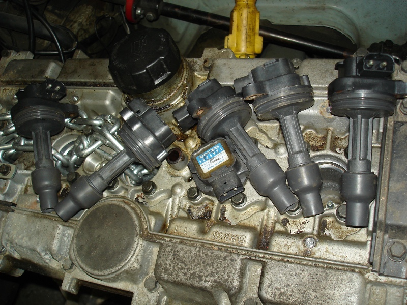
Then I talked to Beust tuning who's going to do the coil on plug conversion, and I forgot to get the coil drivers, which I didn't know were separate on this generation. So these parts are basically useless, I'll need to use newer coilpacks which have the drivers built in. They're better anyway. And Beust provides the wiring harness too.

I've been trying to get a hold of best tuning for two weeks solid for that same 4.4 coil over plug conversion and they will not respond how'd you get a hold of them??
 
Last edited:
Dude come on, don't quote a 15 picture post just to ask a question. Feel free to edit that down.

Aaron who runs Beust is local to me so I know him personally. I'll ask how the best way for you to get ahold of him is.

Edit: I got ahold of him right away, he says the website should be working and you can also use his direct email at Tightmopedman9@gmail.com.
 
Last edited:
I'd forgotten that you were so close (to the Broomfield office, where I am right now), I'd have tried to swing by if I had remembered, loving the build and would have liked to have taken a closer look and said hello.
 
You'd be welcome any time. PM me for my phone number next time you're available.

I guess I can post half an update so it's not a worthless bump. I got my intake adapter tacked together, I'll finalize it after I get an alternator installed and the idle control motor laid out.

Trimmed it a little more for extra angle:

122_593.jpg


Clears the PCV box enough:

122_594.jpg


Should be able to get a hose out without hitting the steering box, I might have to trim the corner of the manifold itself though:

122_595.jpg


And plenty of room for a throttle linkage. I have a plan for that already.

122_596.jpg


My welder has the up-pipe parts so as soon as he frees up a few hours I'll post that too. After that will be the engine mounts.
 
Last edited:
Finally got the carpet out so I can start to saw the tunnel:

122_597.jpg


And today I got the up pipe welding done!

122_600.jpg


122_601.jpg


Good fender clearance, a little tight but that lip with the notch can be trimmed back another 1/4" or so.

122_602.jpg


122_603.jpg


Redrilled the CHRA for re-clocking to the new orientation.

122_604.jpg


Crap, bent one of the fins on the compressor wheel. I thought I was careful but it's been kind of tossed around my workbench for about a year now.

122_605.jpg


I'm going to have to get creative with the oil drain, it pretty much hits the flange now.

122_606.jpg


Boom. Pretty close to final mounting position.

122_607.jpg


122_608.jpg


It's a little crooked which puts the cold side closer to the head than I like, I think I'll drill out the up pipe holes so it can be straighter and maybe allow the cold side to rotate a little more.

122_609.jpg


Hot flange is pretty close to the intake tube here, have to research how much heat silicone can take, might have to figure out some heat shielding. Another reason to rotate it just a little more.

122_610.jpg


But it's a good position for the outlet, straight at the intercooler between the intake and the lower radiator hose. I'm really pretty excited at how well this is laying out.

122_611.jpg


122_612.jpg


Doesn't really leave much room for an air filter but I can go into the fender well if I really need to.

Next, cut the floor to get clearance for the transmission, then pull things out and drop the crossmember for motor mount fabrication. While the car is apart, I'll start working on turbo oil and cooling lines, and cooling pipes in general. Once the motor is situated well, I'll lay waste to my credit card and buy the radiator/fans/intercooler core, all of which I have picked out.
 
Last edited:
Dude come on, don't quote a 15 picture post just to ask a question. Feel free to edit that down.

Aaron who runs Beust is local to me so I know him personally. I'll ask how the best way for you to get ahold of him is.

Edit: I got ahold of him right away, he says the website should be working and you can also use his direct email at Tightmopedman9@gmail.com.

My bad man didn't mean for that to happen
 
Still unemployed, doing some low budget things to the car to pass the time. I've also been doing a bunch of routine maintenance on my other cars, and car work to make some side money. That's basically charity from friends and family who would rather see me get paid than a random shop.

I did a full motor swap in a 2007 C70 for my dad
I installed an intercooler and AC hose in his 95 850 (he hit a curb and damaged them)
I installed and aligned a tailgate on a '94 940
I replaced the accessory belts for both my brother in law and nephew
I installed a stereo and starter motor in a 2003 Subaru Outback for a friend
I installed an AC compressor, hoses, and receiver/dryer in my 01 V70
I installed new front control arms in my 03 C70, the aftermarket ones I put in 20k miles ago wore out prematurely.

So consistently working on cars, and cutting way back on snacking since January I've lost about 20 pounds so far this year.

On with the update:

Back when I did my axle swap I found that the 1800E parking brake cable that came with the axle was too short to work in this car. I recently found out from Ian at Hi Performance Auto that the 140 parking brake cable is longer but otherwise the same design, and is still available without breaking the bank. So I gambled on it and it was perfect. I had to slightly shorten the pull rod but otherwise it worked perfectly.

Attaches to the axle like factory:

122_613.jpg


Connects to the parking brake lever like factory, and worked perfectly with the brackets I made previously:

122_614.jpg


I think I can poke out the old rubber holder, enlarge the hole above the suspension bolt and use the rubber hanger just like the other cars.

122_615.jpg


The only problem is this bangs against the body of the car, but I think I'll just cut that tunnel material out as it does basically nothing.

122_616.jpg


So now I have a parking brake for the first time in 6 years.

Moving on, I bought this mini 90 amp alternator which is actually overkill in the small department, but it should work great. I'm only running the engine, lights, fan, wipers, and stereo.

122_617.jpg


With the alternator question answered, I removed the motor again.

122_618.jpg


I bought a chevy single V pulley to go with the V belt alternator and gain myself another half inch clearance for the radiator fan. This will be great because I've selected the fans and radiator, and designed the intercooler and I'm basically out of space in the front of the car. I was needing another 1/4 inch and if I used the serpentine belt pulley I'd probably have had to notch the fan shroud. The really cool part is that it's already got the right dimensions to mount backwards and tuck tight up against the motor.

122_619.jpg


Here it is compared to the serp belt pulley:

122_620.jpg


I will have to modify the timing belt cover as it just barely hits on this side. I could probably just melt it with a heat gun and make it work.

122_621.jpg


I'll have to copy this bolt pattern to the pulley, and I have to get a center adapter bushing as the pulley bore is 5mm bigger than the crank snout.

122_622.jpg


I'll have to cut that extra material off the top of my engine mount plate:

122_623.jpg


The brackets to mount it should be really easy to design and build. It'll be about an inch lower than in this picture.

122_624.jpg


With the engine laid over like this I can start to lay out and modify the coolant and turbo piping.

122_625.jpg


And after that, I removed the crossmember from the car again:

122_627.jpg


Made a template for the motor mount brackets:

122_626.jpg


They mount like this:

122_628.jpg


And I have the engine mount plates fixtured up to weld in the mounts:

122_629.jpg


So now I have to wait for my welding buddy to be free again but it will be a moderately easy task to cut out those plates, weld them to the crossmember, and then make a T out of tubing and weld it to the engine plates with some gussets. Long term I'm kind of worried about aluminum developing cracks but it's all very beefy so I probably have nothing to worry about.

Also while I wait for my friend I can get started on the alternator mounting, the pulley modifications, chopping out the transmission tunnel and re-routing the brake lines, and begin designing the transmission crossmember. I'm trying as hard as I can to do mostly low cost stuff, but like with the alternator there are some things I just have to spend money on to make progress.

So my goal of June 2016 has come and gone, the new goal is June 2017. Lots of progress should be made this winter, I will be spending on credit as needed to keep this project going.
 
Back
Top