Thank you for the kind words to both Toybox and Coupid.
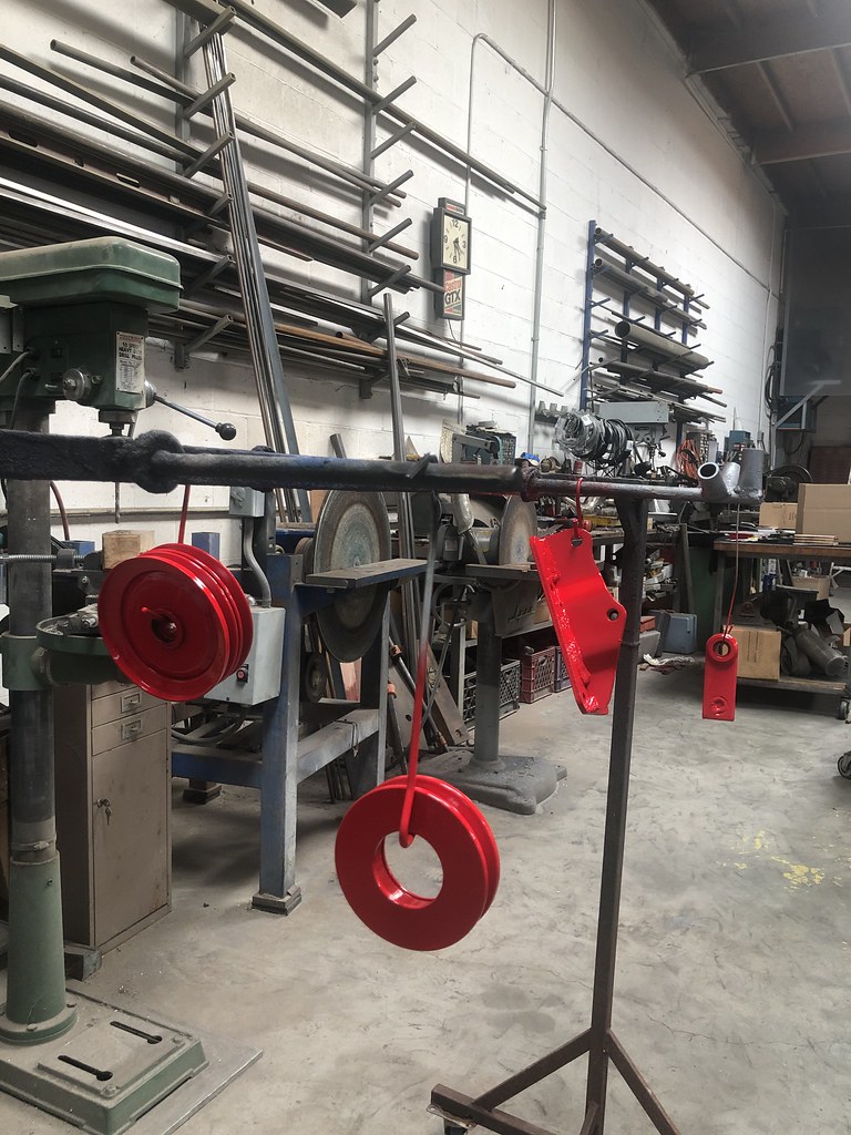
That's a helluva disk sander you've got in your metal shop...

\
If you look closely there are 2 of them; The smaller is an 18" diameter and the big fella is a 24" diameter. We call them disc mills! You always want to be very careful with them as the motors for both are fractional Hp and the discs themselves weigh 20 and 31 lbs respectively so there is a lot of stored rotational kinetinc energy in them once they are up to speed. They spin freely for several minutes after the power is turned OFF. When the 40 grit sanding discs are fresh they will remove metal in a big hurry!
I got back to work in the HVAC project this past weekend, installing the 'new' rebuilt combined module from the '89 donor car. I'm very glad to have had the initial experience of removing the unit from the junkyard car.
")
. I used the info, pictures and advise provided by Polaris as a guide. Kudos for the insight.
I considered using the entire lower panel setup from the '89 car but finally decided against it for 3 distinct reasons:
1) I would have had to relocate the dash lamp dimmer rheostat
2) I want to retain the original '73 appearance
3) I need 7 switch slots and the later cars only have 6 by virtue of the relocated cigarette lighter / power port socket on the new cars. Besides the normal hazard flasher, rear window defrost, and rear window wiper switches I also have switches for the driving lights, O/D on-off, intermittent windshield wiper control and the new A/C potentiometer.
During the changeover I found some interesting evolutionary changes to the combined unit from my '73 to the '89 unit.
1) The little spring/snap clips that hold the blower turbine housings and main body halves together are much nicer on the later cars as the newer style has return flanges on both sides that make them much easier to get on/off and easier to reuse.
2) The hot water valve is much simpler on the new unit. I actually prefer the old style as I think it may provide better thermal modulation. but I am sure that it is also quite a bit more expensive. So I'm guessing that the bean counters told the engineers that better is the enemy of good enough!
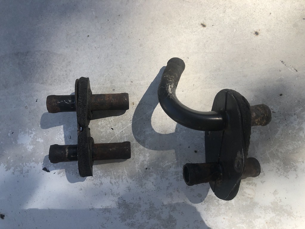
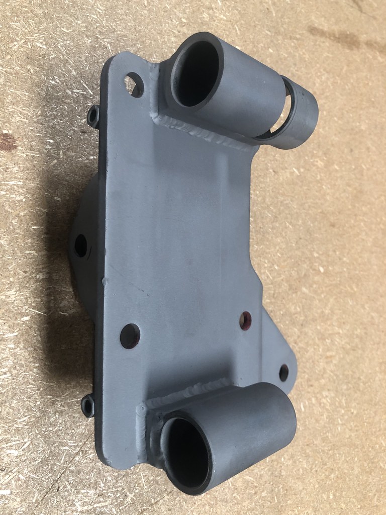
3) The firewall inlet outlet port manifold is a different configuration with different mounting screw location. It requires a couple of new holes to be drilled in the firewall. See pics below:
The later 240 style firewall heater hose manifold in the simple straight configuration on the left and the '73 configuration is on the right.
This pic shows the different mounting hole spacing between the 250 manifold (left) and 140 version (right). The firewall thru-hole spacing for the water ports is identical on both manifolds.
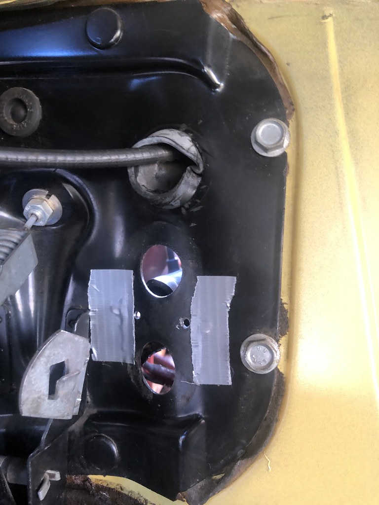
This pic shows the 2 new mounting screw holes with the original holes covered/sealed with duct tape.
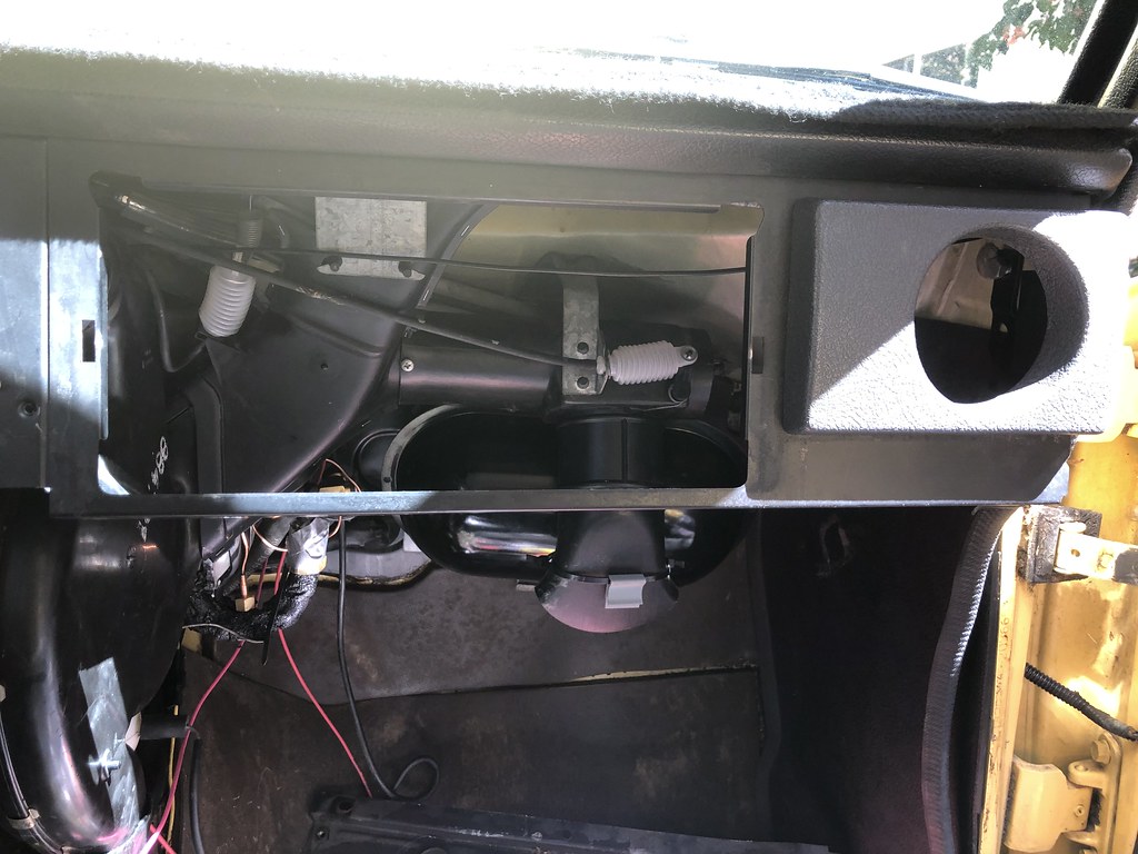
4) The '89 combined module incorporates a plastic vacuum reservoir in the lower support / mount bracket. The '73 system uses a kind of oval shape metal tank mounted separately from the combined unit behind the defrost/outer face vent ducting and glove box, above the passenger footwell.
The 240 style vacuum reservoir, above.
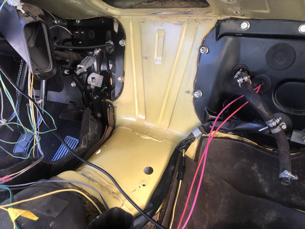
The 140-style sort of shiny black metal oval-shaped vacuum reservoir can be seen behind the footwell vent in this pic, above. Note the cute little whitish plastic bellows for controlling the vacuum operated duct flaps/valves. These are the 140 style vs the diaphragm-disc style used on the later cars.
5) While the upper mounts to the cowl are identical on both the 140 and 240 combined units, the lower mount that incorporates the vacuum reservoir mount on the 240 is different and requires modification for use on the 140. If you are going to discard the plastic vacuum reservoir the 140 lower mount bracket will mate directly to the 240 combined module and the 140 adapter tabs that mate the aforementioned support bracket to the transmission tunnel will match up perfectly. If however you wish to retain the 240 style plastic vacuum reservoir the combined unit lower support bracket must be modified.
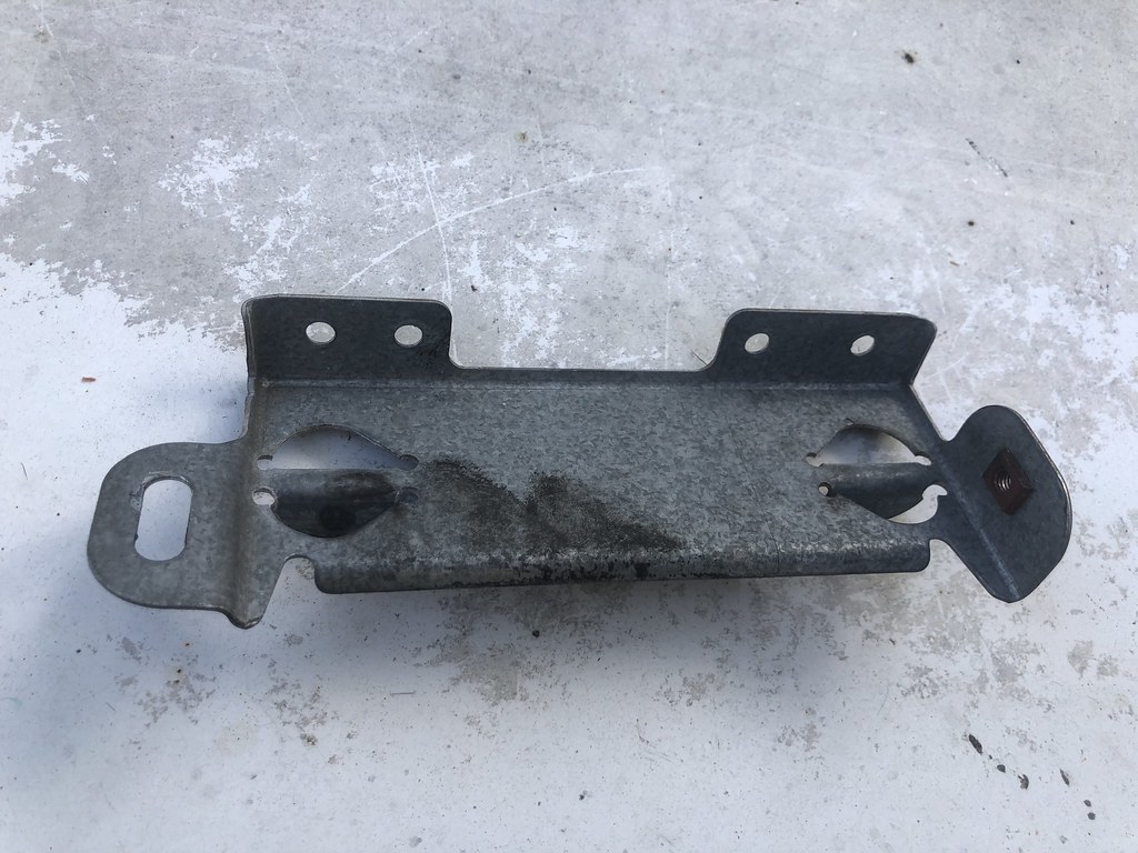
The combined HVAC module lower support bracket as used on the 240, above.
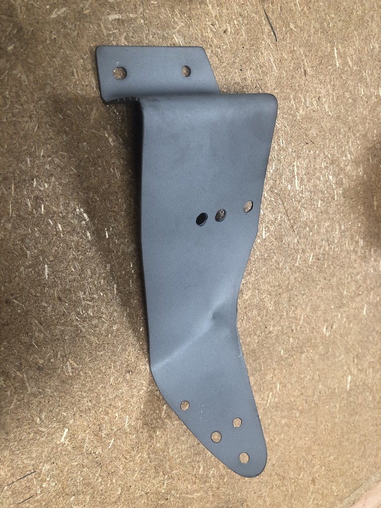
240 style lower support bracket modified to work with 140 style trans tunnel mount tabs. Note 2 changes to this bracket are required to work on the 140:
1) The slotted tab on the left has been folded to a 90deg angle.
2) The right hand tab has had the captive threaded insert punched out and then slotted to mate up to the trans tunnel tab.
6) The 240 heater assy only has a single condensate drain from the evaporator housing vs the 2 drains on the 140 unit. Fortunately the nice molded drain hose has the proper size O.D. to mate perfectly with the passenger side drain hole in the 140 transmission tunnel.
This pic shows the single 240 drain hose on the bottom of the combined unit.
I didn't have the appropriate size rubber plug to close off the unused drain hole in the floor pan. So I used a double layer of duct tape instead.
7) A very handy feature on the 140 vacuum lines for all of the control valve/flappers was this central quick connect coupling. This is not found on the later style cars. It is also worth noting that each of the vacuum hoses is ink print labeled with a number to identify which port they connect to on the 3-pushbutton flow direction control on the dash panel. The pushbutton flow control switch ports have embossed numbers next to each port. This labeling is found on both the 140 and 240 1/8" I.D. vacuum lines.
8) The '73 140 bolt-in black firewall panel on the firewall in the passenger passenger footwell has all of the correct size holes for pass-thru of the A/C hoses already in place. The A/C hoses I scored from the '89 car are properly configured and grommeted to align with the expansion valve and evaporator exit port as well as seal up properly once installed. I will be fabricating new anti-leak hoses once I do the final installation.
Looking back on this portion of the project I am very happy to have had a break in the weather with driveway temperatures in the mid-80s. The heat has returned today with shaded temps in the mid 90s and driveway temps (we have an asphalt drive) well over 100F in the sun.
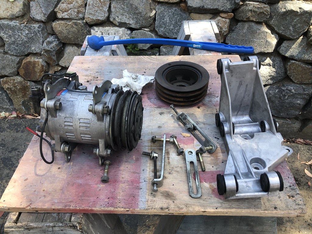
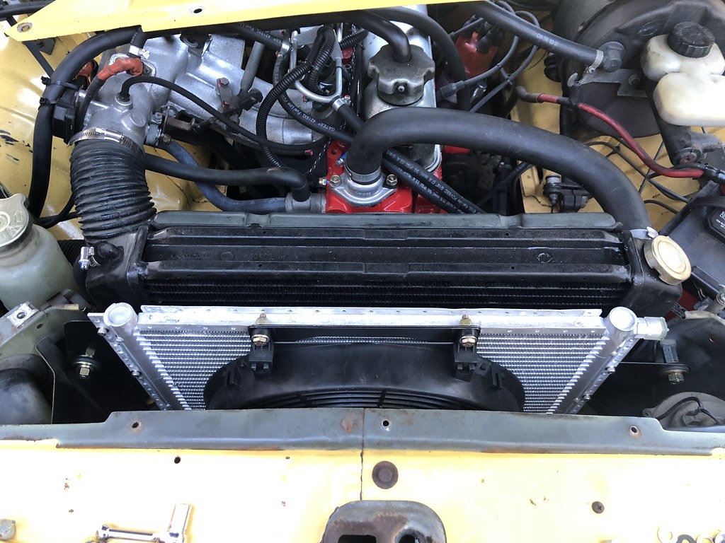
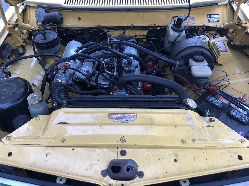
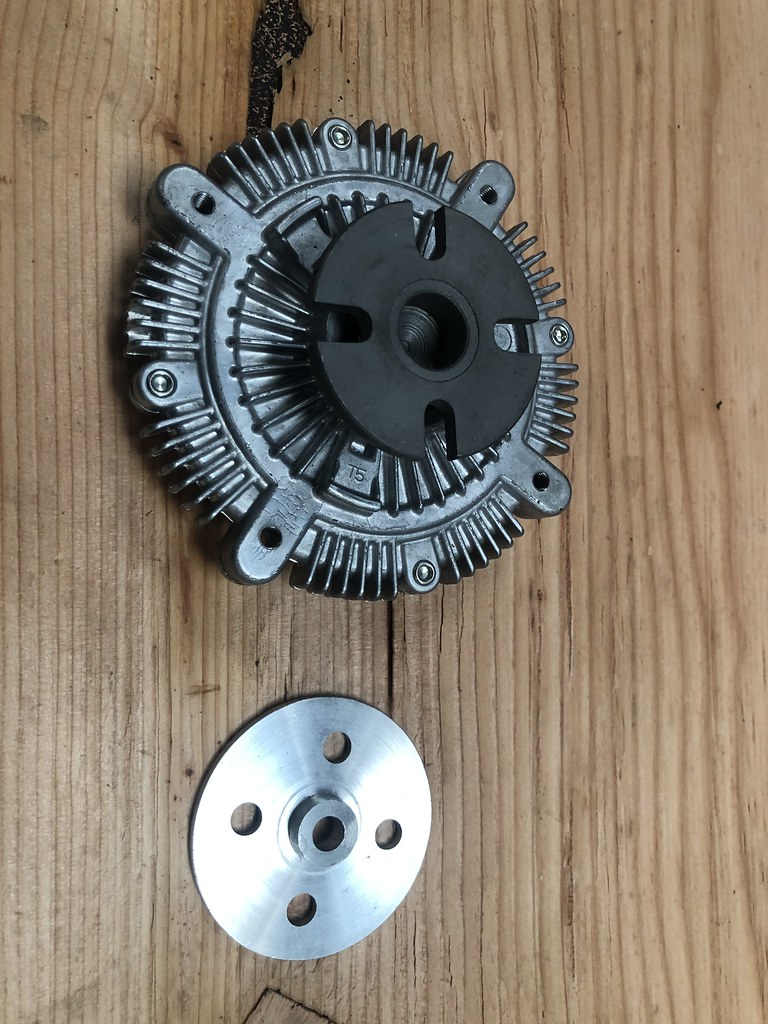
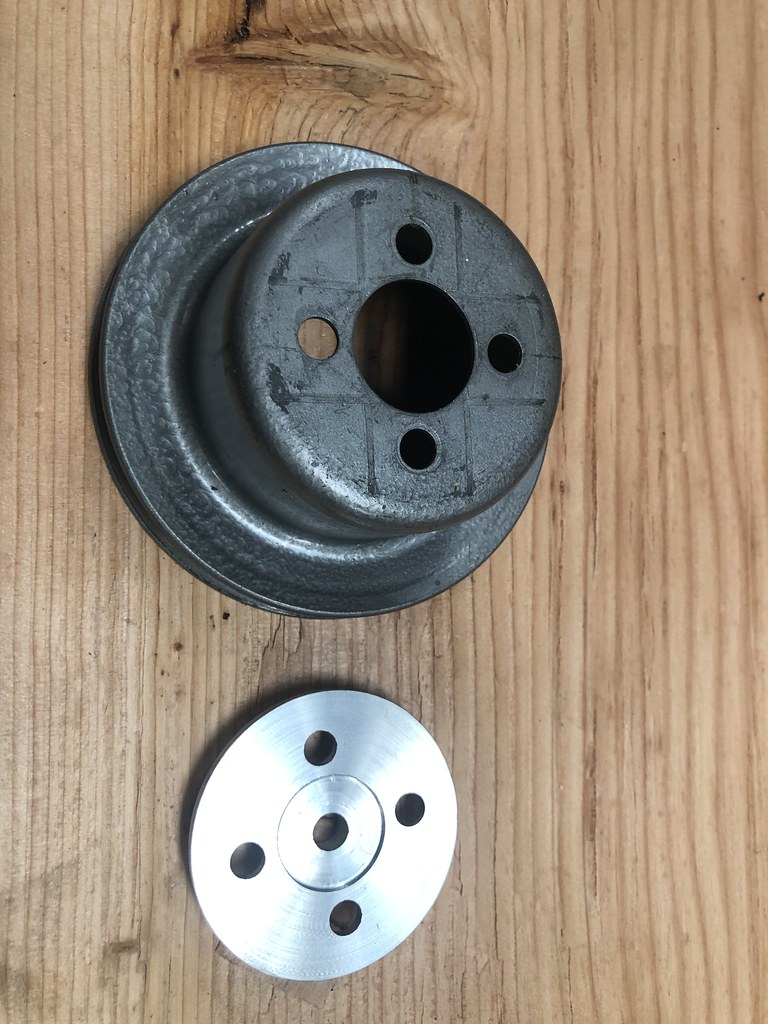
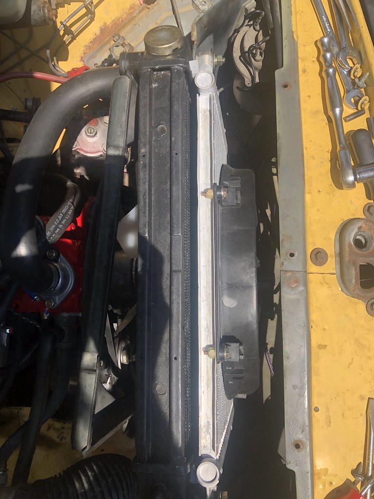
Next up is mounting the under hood hardware: The compressor mount, compressor, dual row crank pulley, receiver/drier, idler pulley and new water pump cooling fan.
Once that hardware is installed I'll finalize the hose lengths and then fabricate and install the hoses. After that it'll be time to charge the system.
While occasionally trying this was not a difficult job, many parts of it were tedious and sometimes hard to reach. It would have been much fore pleasant to accomplish on a cooler day. But I also have a Lotus Esprit and I know from experience that for every task under the dash on that car one must keep their cell phone handy in case it becomes necessary to have someone else come out to help you extricate yourself from the car; to get back out of the Lotus position! That said, after I was finished and came in the house, my wife looked at my hands, took this pic and asked if the job wasn't, 'death by 1,000 cuts?'