• Hello Guest, welcome to the initial stages of our new platform!
    You can find some additional information about where we are in the process of migrating the board and setting up our new software here

    Thank you for being a part of our community!

The 142e decade build...or sooner hopefully.

ECU / Electronics / Upgrades / Mods

So a couple of questions as I spent all weekend working on Megasquirt pinouts and what options I have moving forward.

1). My 142 manual doesn't reference this but does anyone happen to know what voltage or resistance values are expected when coming from the brake warning circuit when it triggers the brake warning indicator? I'm assuming it's the same voltage that triggers the indicator when the e-brake is engaged?

2). For the M41 Type J OD unit the OD switch initializes the relay based on no continuity vs 0 ohms or am I mistaken?
 
1) The warning valve switch and parking brake switch complete the ground side of the circuit to the indicator light. They are both connected to the same terminal so either one can illuminate the indicator light.

2) There is no relay for the overdrive on a 140. When activated, the column switch illuminates the indicator light on the dash and sends +12 volts to the 4th gear lockout switch on the trans. When in 4th gear, the lockout switch then passes power to the solenoid.
 
Thank you!!! :)

1) The warning valve switch and parking brake switch complete the ground side of the circuit to the indicator light. They are both connected to the same terminal so either one can illuminate the indicator light.

2) There is no relay for the overdrive on a 140. When activated, the column switch illuminates the indicator light on the dash and sends +12 volts to the 4th gear lockout switch on the trans. When in 4th gear, the lockout switch then passes power to the solenoid.
 
ECU / Electronics / Upgrades / Mods

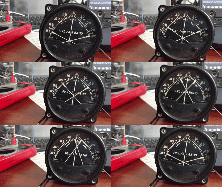
Made some progress with the FAR gauge today. Still needs some work but getting movement is by far the most hopeful I've been with incorporating the aero gaues into my dash. For some reason the gauge sits right above .07 when the voltage is at zero and I'm not sure why that is. The same goes for my dual temp gauge it also sits in the same spot when no voltage is present.

videotogif_2018.06.01_15.16.16.gif


The sweep you see is the following range:

0 - 1.25volts

20 ohms - 145k ohms

The code is very basic for now the main goal being if I can change the duty cycle on the fly and get a response out of it. I prefer this method over the potentiometer since when I have it connected it just gets in my way.

HTML:
int ledPin = 9;      // LED connected to digital pin 9
int analogPin = 3;   // potentiometer connected to analog pin 3
int val = 0;         // variable to store the read value

void setup()
{
  pinMode(ledPin, OUTPUT);   // sets the pin as output
}

void loop()
{
  val = 0;   // read the input pin
  analogWrite(ledPin, val / 4);  // analogRead values go from 0 to 1023, analogWrite values from 0 to 255
  delay(2200);
  val = 27;   // read the input pin
  analogWrite(ledPin, val / 4);  // analogRead values go from 0 to 1023, analogWrite values from 0 to 255
  delay(2200);
  val = 54;   // read the input pin
  analogWrite(ledPin, val / 4);  // analogRead values go from 0 to 1023, analogWrite values from 0 to 255
  delay(2200);
  val = 81;   // read the input pin
  analogWrite(ledPin, val / 4);  // analogRead values go from 0 to 1023, analogWrite values from 0 to 255
  delay(2200);
  val = 108;   // read the input pin
  analogWrite(ledPin, val / 4);  // analogRead values go from 0 to 1023, analogWrite values from 0 to 255
  delay(2200);
  val = 135;   // read the input pin
  analogWrite(ledPin, val / 4);  // analogRead values go from 0 to 1023, analogWrite values from 0 to 255
  delay(2200);
  val = 162;   // read the input pin
  analogWrite(ledPin, val / 4);  // analogRead values go from 0 to 1023, analogWrite values from 0 to 255
  delay(2200);
  val = 189;   // read the input pin
  analogWrite(ledPin, val / 4);  // analogRead values go from 0 to 1023, analogWrite values from 0 to 255
  delay(2200);
  val = 216;   // read the input pin
  analogWrite(ledPin, val / 4);  // analogRead values go from 0 to 1023, analogWrite values from 0 to 255
  delay(2200);
  val = 243;   // read the input pin
  analogWrite(ledPin, val / 4);  // analogRead values go from 0 to 1023, analogWrite values from 0 to 255
  delay(2200);
  val = 270;   // read the input pin
  analogWrite(ledPin, val / 4);  // analogRead values go from 0 to 1023, analogWrite values from 0 to 255
  delay(2200);
}
 
Last edited:
Back
Top