Just a spool of wire around a magnet, yes.
I got about 0.7V AC cranking and about 1.3V AC idling. Voltmeter averaged-out the signal for me.
Sounds OK to me. You've got a good baseline. Just try to stick with the same meter and technique for connecting it when you do it next time.
The reasons this method of verifying the crank angle signal is not in the books might be:
1) An AC voltmeter was not standard fare in an automotive repair shop ca. 1989.
2) Those digital multimeters we have now vary considerably in how accurately they measure signals that are not strictly sinusoidal.
3) Test leads and connection technique can introduce unwanted signal and noise near the same level, for example from the injector flyback or secondary ignition wiring, leading to ambiguous conclusions.
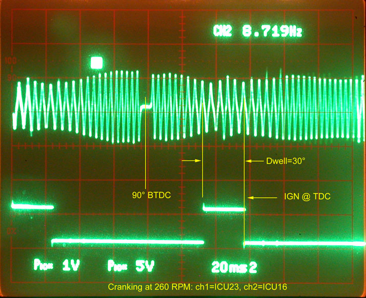
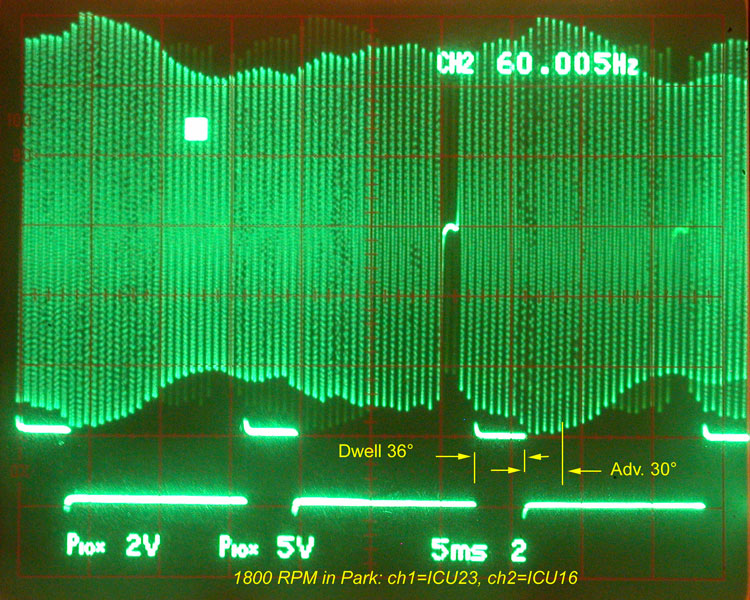
Your lab scope would show you something like these traces, but every lousy CPS I've had will out itself by failing to show the reasonable coil resistance when checked with the ohmmeter - when I've been able to get it to fail in a solid manner.
The failures are internal connections between the fine enameled wire wound on a bobbin over the magnet and the flexible stranded cable assembly. The stresses of potting and its ability to hold up across time and temperature probably account for the infant mortality and out of box failures, and the cable sheathing break that conducts water into the core to swell it with rust accounts for most of the long term failures.
I took these scope pictures when I was younger and more ignorant. In the photo, I blamed the signal variation entirely on tone ring runout, but it is mostly due to the instantaneous angular velocity of the crank as indicated by the wave period of the slots or windows. That's basically why your idling voltage was twice that for cranking -- rpm.
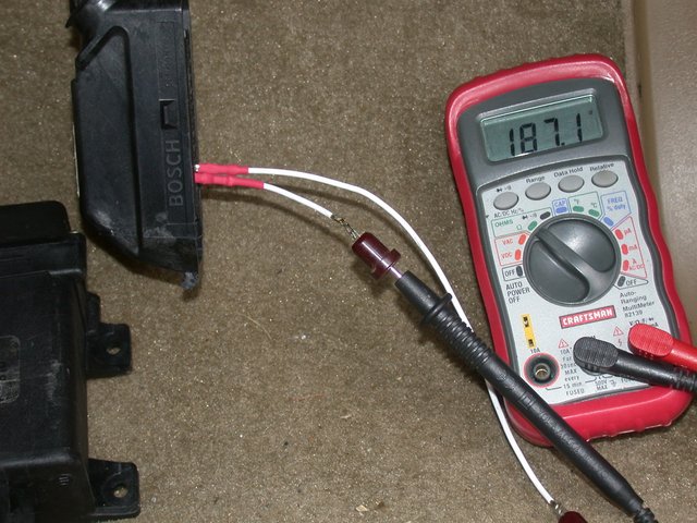
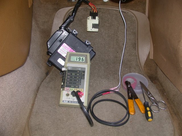
Above is a good resistance reading using single-pin sockets pushed over the ICU pins in order to ensure all the cabling connections are included. That way I can give the cables and connectors a good shake and watch for a change in the resistance reading.
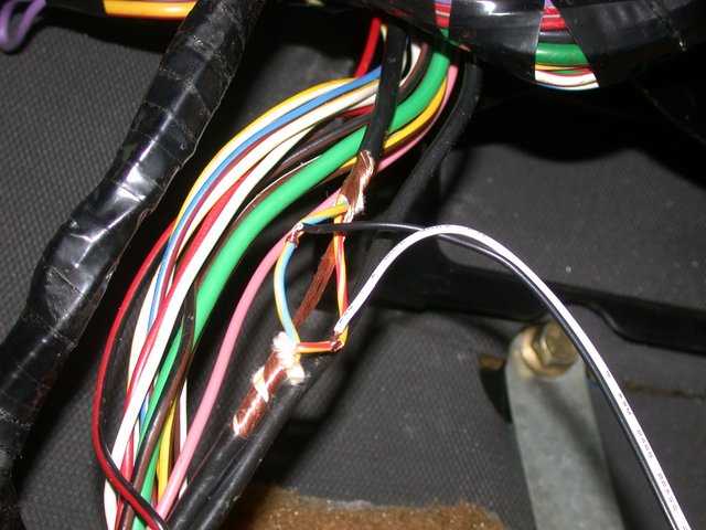
Extreme measures here to catch and prove an intermittent failure. The cable was tapped in order to leave the meter in the car while it was being driven, so the act of connecting the meter would not disturb a flaky connection.
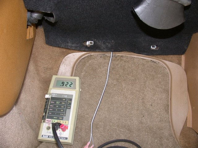
Resistance reading is OK now. Remember the resistance will vary with the temperature of the sensor's winding. I've seen it as low as the 160 reported by sbabbs, I think, and over 200 as well.
But 922 is way out of line. If you see it well above or below 180, give the cabling a shake. This particular one responded by going completely open when shook at the sensor end, and it was only a year old.


")