• Hello Guest, welcome to the initial stages of our new platform!
    You can find some additional information about where we are in the process of migrating the board and setting up our new software here

    Thank you for being a part of our community!

E-Code Relay Placement: Stupid Questions Edition

XxJenoxX

Skin Suit
Joined
Apr 25, 2010
Location
Pittsburgh, PA
I'm finally getting around to (hopefully) doing more than contemplating these ecodes. I finally have all the parts, and thank god I didn't put them on the sedan like originally intended. That would have sucked.
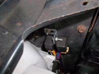
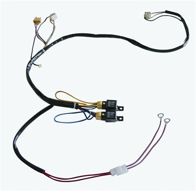
Just went out to the wagon and looked around at where I might want to mount the two relays, and I've arrived at a couple of questions:

1. Where are you guys putting them? I'm maybe regretting getting these nice waterproof ones, for the sheer size of them. There aren't a lot of good places to put them side-by-side, and the only mirrored locations to put one here and one there seem to be towards the front cowl, mounted vertically alongside the fan. It's a '92 with 2.4 and ABS, so while there's a lot of free space in the bay, flat surfaces to mount to are minimal. Strut tower on the passenger side? Seems like a lot of exhaust heat. God forbid I ever throw a turbo near them.

2. My understanding is that most people are using one for high beam and one for low beam. Where is the bulb-out indicator measuring resistance? If I put the relays off to one side, or one on each side of the cowl/radiator pillars (ffs, I can't think of what it's called), is it going to measure too much additional resistance on the side with longer wires from bulb to relay?

3. I was just going to probably put the fuse block somewhere inside the car, for consistency's sake. Any objections?

Bestow upon me your wisdoms! I've looked around, but the death of photobucket has made this less than helpful.
 
OK I recently did this. I used a summit racing premade harness that Gary(gsellstrm) recommended. To mount the relays on the 93 wagon I put them on the vertical sheet metal to the side of the radiator and
near the battery. There is a vertical panel there that on the inside of it supports the condenser. I put the relays on a 90 degree bracket next to each other. On the battery side of the sheet metal. That way the positive hot lead can go right to the battery. I used the stock ground locations for the new headlight connectors but had to lengthen the wire for them. To splice the wires together the heat shrink sleeves with solder in the center are great for this stuff giving you a sealed splice.

I will try to get a picture of the relays in place and post it. Hope that helps if you can visualize what I wrote.
 
Awesome, thanks. My only remaining concern would be the length of the wires to left and right and the resistance measurement? Have you had any issues? Where did you run the wiring to the passenger side headlamp to keep it out of the way, under the cowl? I'm making my own harness, since I have a ton of great wire and access to lots of tools and connectors.
 
The measurement required to trip a bulb out may well be nowhere NEAR sensitive enough to be an issue here, but I work on electrical safety testers that basically play in the mud on some measurements, so wire length is the bane of my existence. :lol:
 
It doesn't trip the relay at all. Probably doesn't work either though. lol. I ran the passenger side under the fan shroud. I started by going under the air filter box then continuing to the other side and coming up next to the radiator hose. I like that area because it is behind the front sheet metal. You could take down the tray and use some clamps to hold it along the lower radiator support. I don't know how long the harness was but you probably need about five foot run to be sure there is some extra.
 

Attachments

  • 100_0092resized.jpg
    100_0092resized.jpg
    50.3 KB · Views: 132
The after market harnesses use a male headlight plug that plugs into one headlight connector on the side of the car that the battery is on. This gives you trigger and ground for the trigger side of both relays. If you are going to make your own harness I highly recommend the Hella headlight connectors. They have nice spring loaded connections. They also handle high wattage bulbs without issue. I got them from Rallylights.com. Susquehanna motorsports I think is the company in PA.

Narva 100/90 bulbs work great for little cost.
 
Last edited:
The after market harnesses use a male headlight plug that plugs into one headlight connector on the side of the car that the battery is on. This gives you trigger and ground for the trigger side of both relays. If you are going to make your own harness I highly recommend the Hella headlight connectors. They have nice spring loaded connections. They also handle high wattage bulbs without issue. I got them from Rallylights.com. Susquehanna motorsports I think is the company in PA.

Narva 100/90 bulbs work great for little cost.

Thanks! That and the pictures really help.

I just went poking and pulled the boots back. 3 wires to 3 wires or the HD connectors I got, yadda yadda...

I had always heard ECODES FIT, BUT YOU MUST MUST MUST WIRE IN RELAYS, AHHHH! :run:

But am I chasing my tail on this, and I can work up a harness after I install? Like, splice in those H4 connectors, throw the ecodes in, and everything will actually work and the rest is just improvements?
 
How far upstream are you guys running new wires? I know you can check the Daniel Stern diagram for the whole shebang, but is everyone really wiring entirely new to the battery, alt, headlight switch, selector, whole nine?
 
Actually, it WOULD be cool to just replicate that harness, if I can get some more specifics from those who have used them...
I found the link to the harness itself.

UPD-34263.jpg


Zooming in and seeing if I can replicate, but it's hard to tell what goes where with the loom wrap.
 
When I installed e-codes, all I did was splice in the H4 connector with the stock wiring. The main reason to have the relays installed is higher light output and lower voltage use. So you can run the e-codes by just splicing in the connector and you'll be good to go.
 
Can anyone tell me what the pinout on the relays is? And what wires are going to that fusible link? I think I've figured out the rest, but I can't see some of it from that photo. Is that one still setup as one for highs and one for lows, or is it one relay per lamp?
 
They are standard four pin relays. So pin 85 gets wired to 12v trigger from one of the old headlight wires on each relay. 86 is grounded. 30 is the high current 12v power source from the battery or alternator and 87 is the new headlights. Terminal 30 should get a fuse protected wire to it.
 
Great, thanks. I have the additional 87a, but a bunch of digging seemed to indicate that I can just not use it, correct?

Or does it run the same as 87 and I could run one from 87 and one from 87a instead of running one new headlight wire spliced to both for each high and low?
 
...... 30 is the high current 12v power source from the battery or alternator and 87 is the new headlights. Terminal 30 should get a fuse protected wire to it.

another elegant solution is a "fusible link" to protect your feed wire to the 30 contact. These are selected based upon the amperage..... FORD uses them heavily, and Volvo on occasion (the 7/9 E-fan relay is protected by a fusible link).

And for the OP, you'll probably gain a solid volt, maybe 1.5V directly to your headlights by use of the relay setup. The H4 lighting increase is substantial with that extra voltage..... do it!
 
Ohhhh wait, 87a is closed, not open like 87, so both are gonna have to come off 87.

I have a little 6-position fuse block, so I had planned on using that. Leaves some room for anything else I might wanna fuse in the future, as well. I also have a single fusible link, but it's just a cheapie Pep Boys one I picked up for some experimentation with eliminating ceramic fuses.
 
87a is usually the extra load connection that is closed when 87 is closed. Are you sure it isn't a closed connection when 87 is closed? There should be a diagram on the side of the relay to show how it is connected.
 
Back
Top