• Hello Guest, welcome to the initial stages of our new platform!
    You can find some additional information about where we are in the process of migrating the board and setting up our new software here

    Thank you for being a part of our community!

Rotary powered 242

Well I did read the whole thread, and ended up a bit confused.
Are the rotors and housings (beautiful steel oval in alloy surround) just experiments for fun, or is the intention to run a fairly stock 4-rotor Mazda engine then swap for the new parts bit by bit?
 
The casted housings are just for fun, and as for now also the steel billet rotors.

The first engine will probobly be with the modified Mazda-parts to fit my engine-spec as for housings and 9.7:1 rotors.
When I first started this build there was no 9.7:1 rotors on the market, so I started on my own. Then these came up within a fair pricerange, and I desided to concentrate on the rest of the motor instead.
 
Don't know really. Have some work with the rear axle to complete, and also the steering of the car. I do what I feel inspired to you can say.
 
Long time no see, have done some small updates now and then on both Facebook and Instagram. I'm sorry, but it's so easy to throw in a picture and move on.

Lets do a throwback sunday.

I did a little test with my front fender. My wheels are to big, and the body is so much lower that I can't mount the fenders over the wheels today.
I let it sit there and sink in. The rear wheelarc will be a big challenge as well..


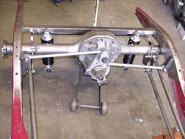
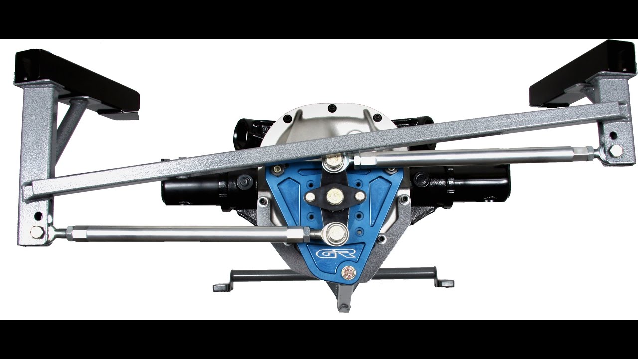
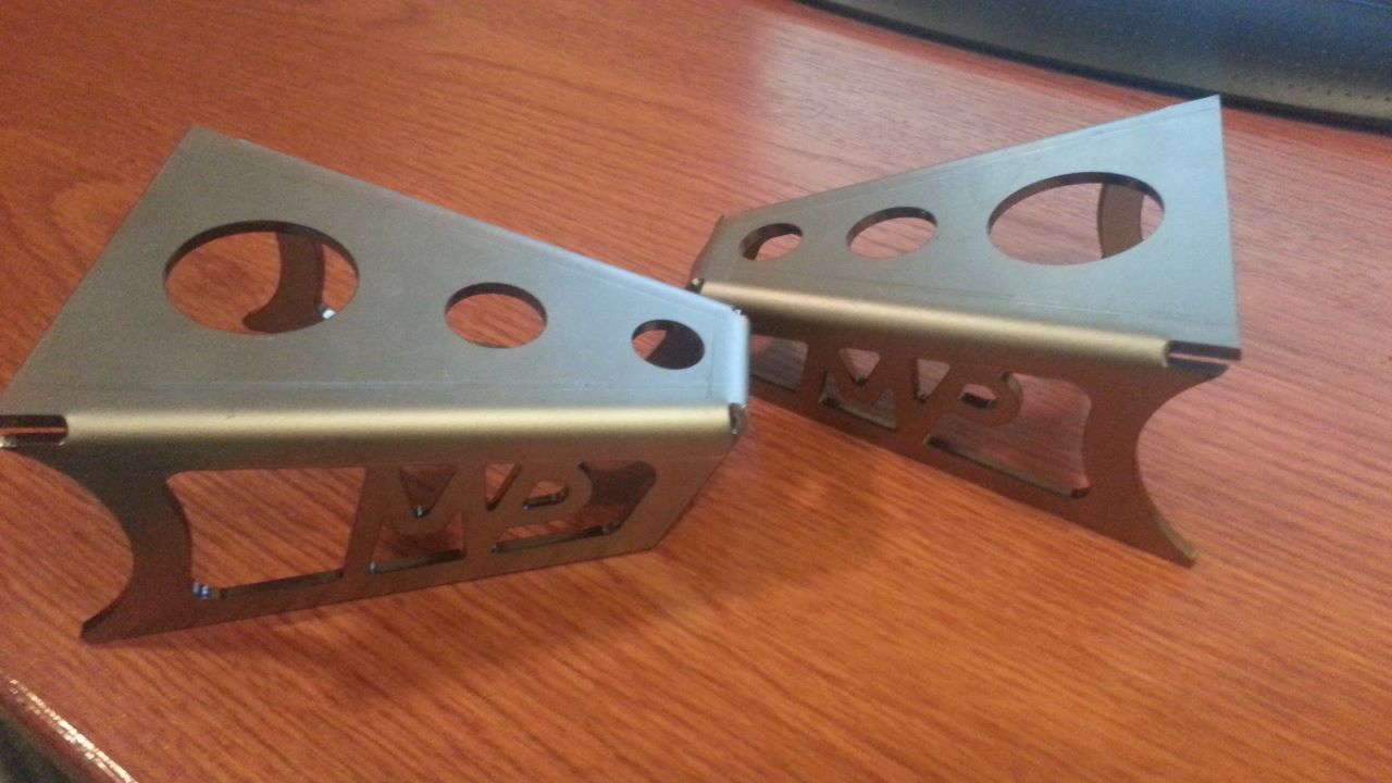
Then I moved on with the watt-link. Did some sheetmetal-parts in Solidworks.


A friend of mine helped me with the lasercut and bending. Will be nice!


Back to the 4-rotor...

I havn't done much, but some small thing here and there.
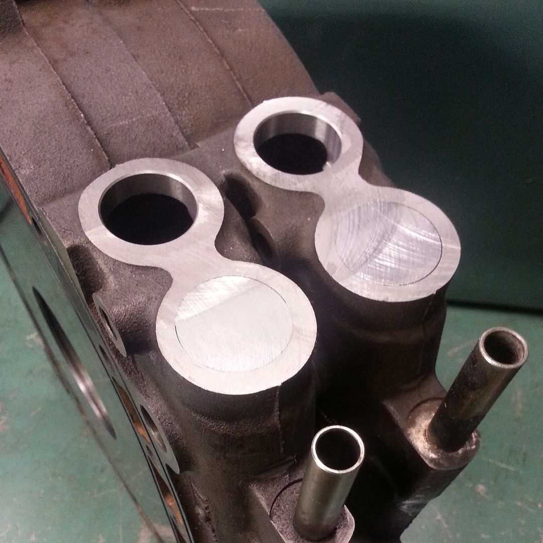
Have done the first part of my new centerbearings.


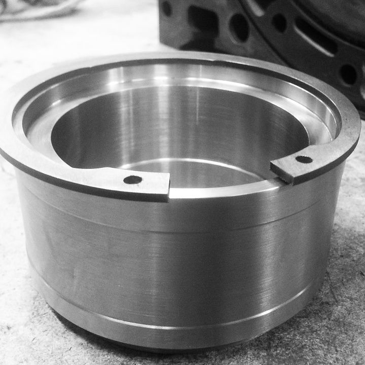
The toleranses are tight! Need to demount to get all oil-windows in place.


Have also prepared the irons.


Then I went through my rotors, and picked out these four. Close call without any mods yet. Only 20grams away.


After some ultrasonicwashing. This is the rotor on the far left on the picture above.


After a few seconds with a scotchbritepad by hand.


Have bought two AutoVerdi-drysump-pumps.
One will GusFD3s use on his Rx3-20B, and the other will I keep.


Sketched up the pump to get it into my assemblies in Solidworks


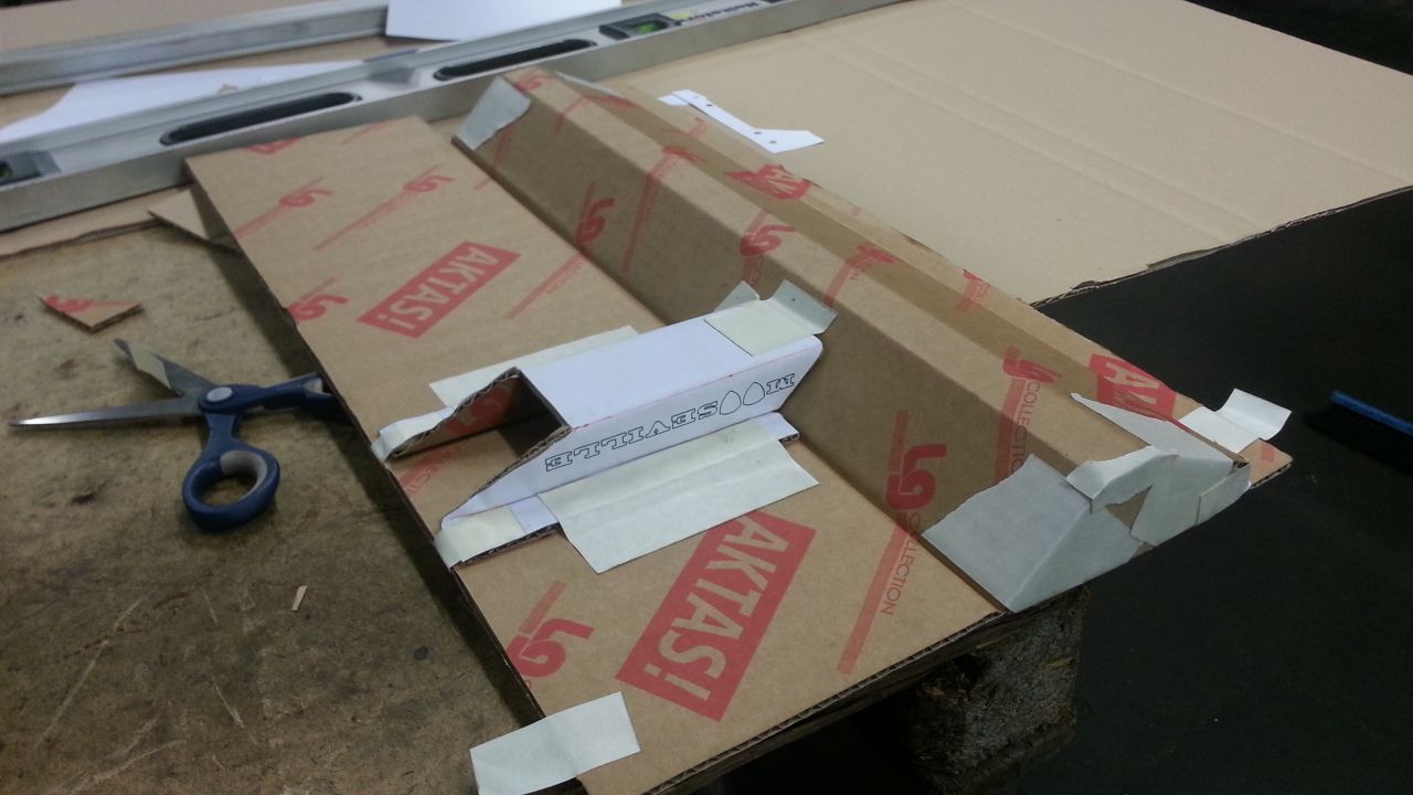
Started on the drysumppan and front cover that will be some billet-kind.


Havn't desided if the pan will be billet or sheetmetal, the sheetmetal have some advantage, but billet is engine-porn :-)
Did a test with wellpapp of the sheetmetal-version.
Very tight and small, easy to fit AN-12 into.


So, not much has happened, but still going in the right direction.

Can remind you of the facebook-page and instagram if you want instant updates without text :-)
But I'm trying to get better on updates here as well.

http://www.instagram.com/tegheim83
http://www.facebook.com/moosevilleperformance
 
wattlaumlnk-01_zps47960877.png

[/url]

Hey dude! Is it me, or is the Watt's link drawn here is wrong??

Isn't one of the mount point connected on one of the chasis rail of the car, middle on the diff and the other side of it on the other chasis rail? Like so:

0601sr_15_zhot_rod_rearend_zps7371b4e9.jpg~original

maxresdefault.jpg


Just a thought i'd say :)

ADam
 
I'm guessing he is doing a reverse mounting with the centeral mount point being on the car frame and the outer points being on the axle tube
I've never seen it done ever... but playing with some lego just now it appears it does work
It almost seams like a better way as it does not stress the diff cover at all...
Not sure about sprung vs unsprung weight differences though
 
It's just the centerlink isnt mounted to the diffcover, which looks on the first look like it but it doesnt.. my first thought was also wtf?!
 
It workes exactly the same as "normal" mount, just that this way you don't move rollcenter when turning and bumping.
 
Back
Top