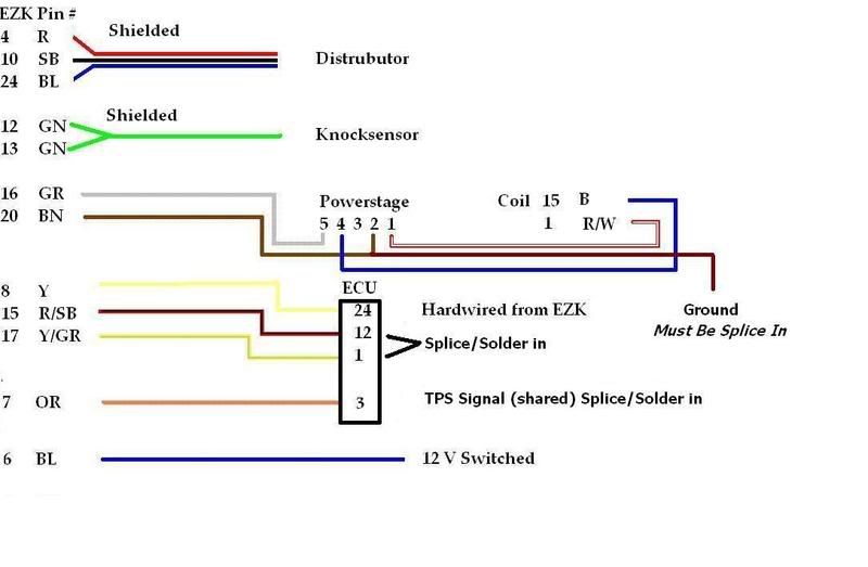
I did this swap two weeks ago in about 6 hours, following the two EZK swap threads. I made a word document that I kept beside me during the swap and it fired right up; here it is since I can't upload the doc, only thing missing is the same picture you posted earlier:
Also, for cleanliness, I noticed that instead of running the wires to the connector under the intake you could directly connect the wires from the EZK to the ECU and I did so which meant I only had to run 5 wires out of the cabin.
-DO NOT connect 15 to 12 on N/A ECU, keep the stock wire there
-ONLY connect 15 EZK to 12 ECU when using Turbo ECU
You need to push 7 of the 10 wires through the firewall into the engine bay and they are:
solid blue
thick gray
brown
orange
gray/yellow stripe
thick black
thick green
Keep the black/red stripe, yellow, and yellow/red stripe inside the car.
Chapter 4: What these 7 wires go to
solid blue (positive terminal on coil)
thick gray (powerstage connector)
brown (powerstage connector, EZK, and ground)
orange (connector under intake)
gray/yellow stripe (connector under intake)
thick black (hall sensor on distributor)
thick green (knock sensor on side of block under intake)
Chapter 5: The powerstage
So you have a fat connector that the thick gray wire from the harness goes to. This is the connector for the powerstage. The brown wire coming from the powerstage connector needs to connect to the brown wire coming from the EZK connector(if it is not already connected). Then you want to ground a wire and tee this grounded wire into the aforementioned brown wire that goes from the powerstage connector to the EZK connector. Then you will notice that you have 3 more wires coming from the powerstage connector itself: blue and 2 white/red stripe (one thicker than the other). Connect the blue wire to the positive terminal on your coil. Connect the thick white/red stripe wire to the negative terminal on your coil. Finally connect the thin white/red stripe wire to the white/red stripe wire that goes to your tach.
Now is also a good time to take the solid blue wire coming from the EZK harness (should be same color as the one from the powerstage connector) and connect it to the positive terminal on the coil as well.
So to recap we have blue from main EZK connector and blue from powerstage connector to the positive terminal on the coil. We have thick white/red stripe connected to negative terminal on the coil and thin white/red stripe connected to the tach wire. Finally, a brown wire going from the powerstage connector to the EZK connector with a grounded wire teed into it.
Chapter 6: Swimming under the intake manifold
Get your snorkels on because we're going swimming for a little, 2 wire, black connector located under the intake manifold. It should have an orange wire and a gray wire in it. Once you find it, unplug it and cut off the connector with the MALE spade terminals in them making sure to leave yourself enough wire to solder. Now you will most likely have to extend both the gray/yellow stripe and orange wires coming from your EZK harness and then connect them to their respective gray and orange wire mates from the small connector you just removed. Now plug the connector back in to its female half under the intake manifold.
Chapter 7: Hall Sensor
Unplug connector on hall sensor on distributor, take the thick black wire with 3 prong connector coming from your EZK harness, and plug this connector in. Done.
Chapter 8: Knock, knock...who's there
Get your snorkel back on and start digging under the intake manifold again. Unplug and then unscrew the old knock sensor from the block. Now take your new knock sensor from the donor car and it's respective mounting bolt and bolt it into the hole you just opened up in the block. Now connect the fat green wire from the EZK harness with 2 prong connector to the knock sensor you just bolted on. Done.
Chapter 9: ECU/EZK communication
You need to open up the connectors of both the EZK and ECU harnesses. They are held together with 3 little screws. Once inside you need to track down the yellow/red stripe wire that is in the EZK harness. Take a precision screwdriver and remove the pin from the EZK harness connector that this wire goes to. If you must cut the wire to extend it try and keep as much of the wire as you can to make soldering the extension easier. But keep the little pin no matter what. Take this pin with wire (extended if you had to) and connect it to the yellow wire coming from your EZK harness. Now insert this pin into pin slot number 24 of your ECU harness connector which should have nothing in it. Now take the black/red wire coming from the EZK harness and connect it to pin 12 of the ECU harness.
EZK117K(LH2.2)-Pinout:
1:
2:
3: Supplies fault indication signals to test terminal when test diode is connected
4: Supplies power to Hall generator in distributor
5:
6: Receives supply from battery across ignition switch
7: Grounded by throttle switch when throttle is closed
8: Receives load signal from fuel system control unit
9: Receives 12V supply when thermostat closes (B230FT only)
10: Grounds Hall generator in distributor (shield)
11:
12: Grounds knock sensor (shield)
13: Receives signal from knock sensor
14:
15: Transmits knock-controlled fuel enrichment signal to injection system control unit (B230FT only)
16: Transmits ignition pulses to power stage
17: Transmits speed signal to fuel system control unit
18:
19:
20: Grounds control unit
21:
22:
23:
24: Receives engine speed/crankshaft position signal from Hall generator in distributor
25:
LH2.2-Pinout:
1: Engine speed signal Input, Voltage, 6.5V @cranking, >8V @idle speed
2: Temperature sensor, 4V @-20C
3: TPS signal input, 0.0 - at idle speed, Above idle speed
4: Drive position(auto), Battery voltage - R,D,1,2,3 , P,N, and manual
5: Signal Ground, 0.0 - Separate from power ground
6: Mass air flow, ground, 0.0 - Separate from power ground
7: Mass air flow, 2.0V @Idling, 5.0V @Full Load
8: Mass air flow, burn-off, 4.0 - At burn-off, 0 - In other cases
9: Power supply from main input 12V
10: AIC Valve, 6 - 11 at idle
11: Grounding point, 0 - Separate from power ground
12: TPS wide open, 0V @wide open throttle, 5V @Idling
13: Control signal Output, 7.1 Hz, 2.4-4.5 ms
14: Mass air flow sensor, approx. 2
15: Grounding point for coding, 0
16: Raising engine idle speed, 12V for A/C engaged, 0V for A/C disengaged
17: Pump relay, approx. 1 - Activated, battery - ignition on
18: Main fuse box, positive Voltage, Battery voltage
19: CHECK ENGINE light, Battery voltage - out, 1 - on
20: Oxygen sensor - M1988, 0.6 - 1.0 - Rich, 0.0 - 0.4 - Lean, PRE-Ignition,
21: Main relay operating circuit Output, approx. 1 - Ignition on, Battery voltage - Ignition off
22: Oxygen sensor pulse ratio, data link connector
23: AIC valve, 6 to 12 - Idling
24: Load signal Output
25: Grounding point, 0 - Separate from signal ground