
Trevor+
Volvo Friends
- Joined
- Jun 7, 2008
- Location
- tir porthladd triphlyg
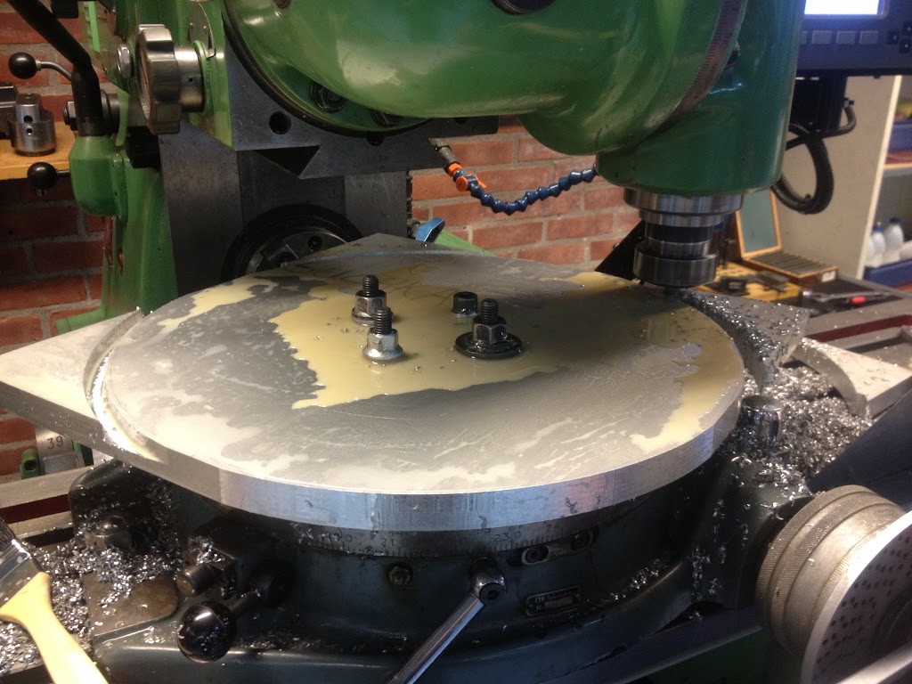
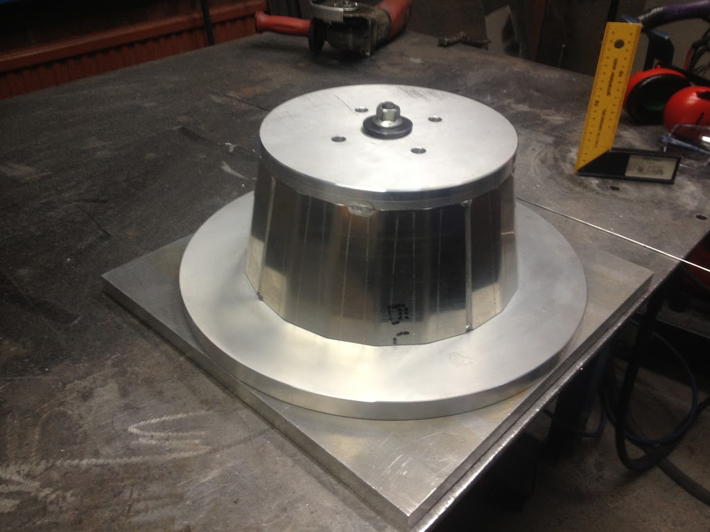
Is that round thing in the middle a knob or a needle?
Hello Guest, welcome to the initial stages of our new platform!
You can find some additional information about where we are in the process of migrating the board and setting up our new software here
Thank you for being a part of our community!
Other then those fully LCD gauges, does no ones make MS driven gauges?
Is that round thing in the middle a knob or a needle?
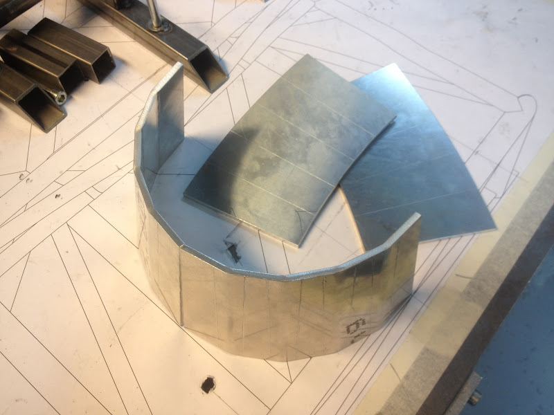

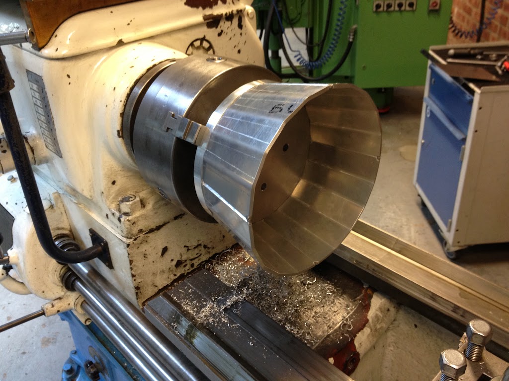
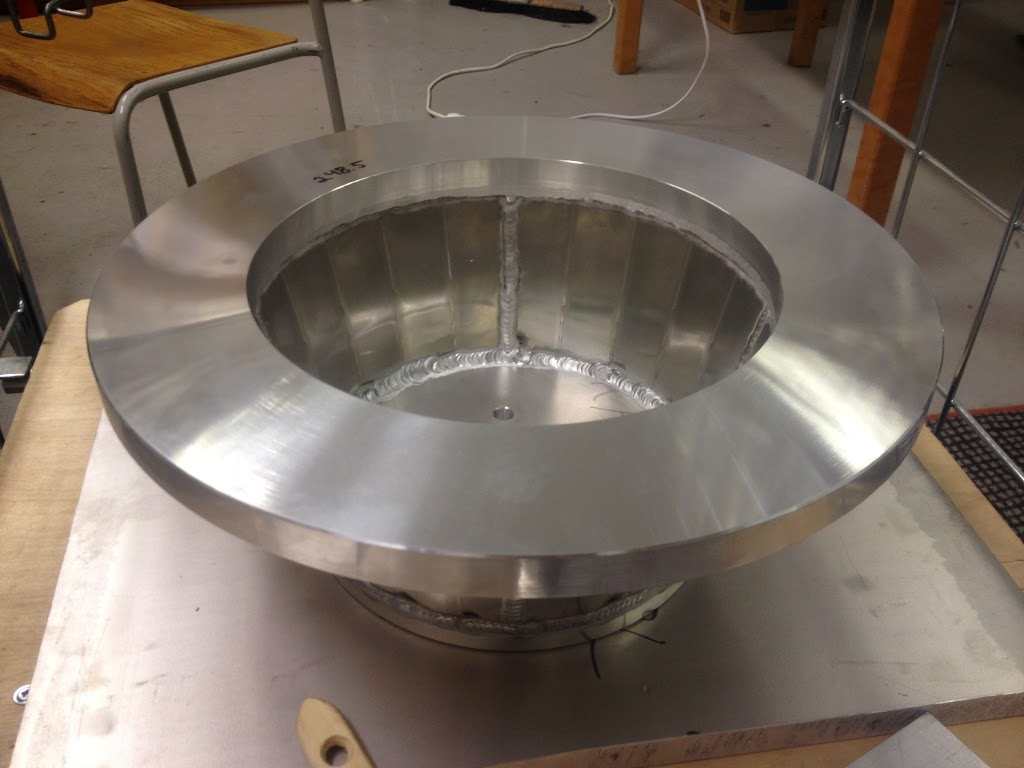
Hoping to put some serious hours in this weekend, so stay tuned for more updates.
*Cursor on refresh*
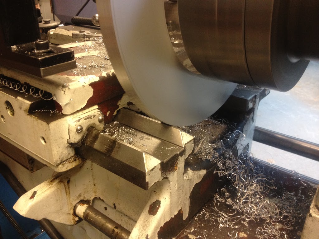
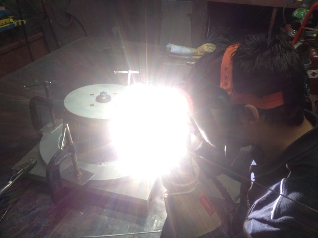

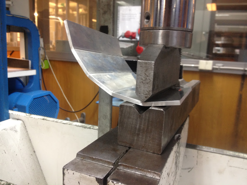
bet you had fun welding that once it got nice and toasty!
")
