• Hello Guest, welcome to the initial stages of our new platform!
    You can find some additional information about where we are in the process of migrating the board and setting up our new software here

    Thank you for being a part of our community!

The official DSM CAS information and install guide

GrossPolluter's The official DSM CAS Guide (this thread) shows a picture of the Yoshifab hi-res disc in the first post, shown again here:
IMG_5992.JPG


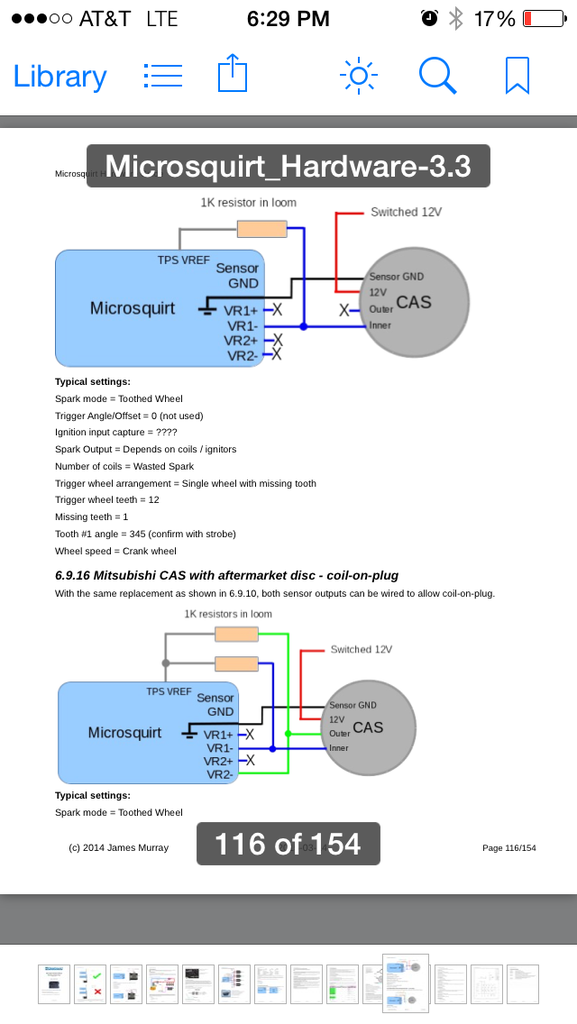
The MicroSquirt v3 Hardware Manual shows a different style of DSM CAS hi-res disc -see Section 6.9.15 Mitsubishi CAS with aftermarket disc

Notice that the single CAM slot varies between inner and outer wheel depending on the hi-res disc. And that the Crank wheel on the disc shown in the MicroSquirt manual is a 11+1 (or 24+2?) missing tooth wheel.
 
This is how I wired mine originally. After messing with it for awhile I swapped my vr signals and it started right up. If the crank signal is on the inner portion of the disc then it would be correct. Crank signal is always vr1.


I've been having some issues trying to get my yoshifab 24 tooth wheel to work with my cas. Trying to run fully sequential. I get RPM. I can get the motor to sync with a drill and by cranking at different RPM but when there is a change in the rpm I get a sync loss code 17. I've tried changing the cam signal to rising/falling and crank signal to rising/falling and every combination. I've tried different trigger angles and nothing seems to work. Set up like the thread suggests the car will kick over and almost start but I'm pretty sure it looses sync and just won't remain running. My tooth wheel looks a little bit different than the one in the pictures of this thread. Is it possible that the cam tooth is in such a position that it overlaps on the crank teeth to cause a sync loss issue no matter what you set the trigger edges to sense?

Any suggestions?
Any help would be appreciated.
 
Any suggestions?
Any help would be appreciated.

Kind of hard to help when we don't know what ECU you have, what inputs you've connected it to, how you made the circuit if DIY, and the picture of your trigger wheel isn't loading so it's hard to tell if there's an issue with the wheel or not.
 
I am wiring up microsquirt on my 16vt swap. I am wondering how I would wire my cas with the YoshiFab high res disc and the VAG 4 post wasted spark coil.
 
I am wiring up microsquirt on my 16vt swap. I am wondering how I would wire my cas with the YoshiFab high res disc and the VAG 4 post wasted spark coil.

With the yoshifab high res disc vr1 - is the crank signal and that's the outer part of the disc.
Inner is cam and vr2- I suggest running the 1k pull up resistors.

The coil wires how the manual says. 12v, ground, signal 1, signal 2
Page 62 http://www.msextra.com/doc/pdf/Microsquirt_Hardware-3.3.pdf
 
I have MS3X W/ 3.57 board as far as I understand I can tee off of the 5v from the TPS ref at use that for cam and crank?

also since the signal coming in from the crank and cam can't use the vr circuitry I'm guessing it uses the hall instead right? only other option maybe that was a stupid question
 
I have MS3X W/ 3.57 board as far as I understand I can tee off of the 5v from the TPS ref at use that for cam and crank?

also since the signal coming in from the crank and cam can't use the vr circuitry I'm guessing it uses the hall instead right? only other option maybe that was a stupid question

I'm pretty sure you can use the VR for crank and Opto for cam inputs... not sure with the ms3x though.
 
can you bench test a DSM CAS, with just a 12v source and ground wired up... and get a signal coming from both the crank and cam terminal?
OR
or does the cam and crank wire need to be connected to pull up circuits in order to get a reading?
 
you need the pullup circuits connected. without the pullups it's difficult to see even on a scope
 
thanx dudearoma!
im thinking the pullup circuit i have wired is compromised... im reading 3v at the tach pin 24(ms2 v3 setup)
but im getting a good 5v at cam input so to speak.....
 
Last edited:
A voltage of 3.xx volts on the MS connector pin may be OK depending on which version of the opto-isolator hall sensor circuit you used. Some of the more recent MS guides use the pullup resistor on the CAS pin to turn on the LED in the 4N23 opto-isolator. In this configuration, the voltage on the MS connector will be 3.xxx volts when the LED is on, and < 0.4 volts when LED is off (CAS grounding the signal).

If you're still having problems and not getting a good signal in the composite logger, I'll measure the actual voltage on my MS box, instead of just saying 3.xxx.
 
there are many different write ups on how to install the DSM CAS(2g)... its insane....
tach inputs, cam inputs, spark outputs, inverted signal.....
i had everything working ok with the JimsTim, but then the ignitor almost set my apt on fire.....
DIY website says to use the VR input but that never worked..
so currently i have my MS2 wired with the tachin > XG1(which to me means going to the opto-isolator((U3)) pin2 and 5V to pin 1 of U3)
has anyone had success??? i have this twin cam turbo'd 240 ready to hit the streets baby!!!!!!!
 
yeah don't use the ****ing vr input circuit.

I always built a second opto circuit for the cam signal on mine, if you don't want to do that, you could just get one of the new jbperf dual input boards and follow the instructions there for non-vr inputs (it's not prone to phase shifting like the onboard vr circuit). you'd basically put the pullups inline to the board, and then the outputs of the board will go to TSEL and the cam pin.

if you've got a good electronics supply place nearby, it's cheaper to replicate the opto input.
 
yes. or get a jbperf dual vr board with the max whatever chip on it (the latest version he sells, like v2.1 or something), that's basically the same thing on the v3 microsquirt and ms3pro, cas works very well with both of those.
 
Back
Top