
wennstroma
Active member
- Joined
- Apr 25, 2006
- Location
- Idaho
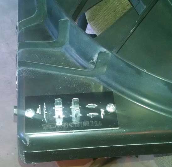
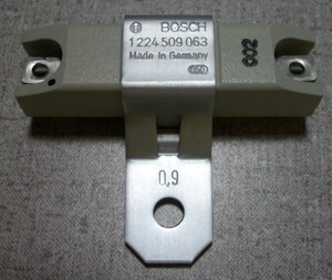
Is the resistor going to be mounted in the fan shroud/airstream? I don't know if there are wattage ratings for these kind of resistors, but you're going to be putting a lot more heat into it than the original application did.
I have a DCC running an aftermarket 16" fan on mine, but it doesn't draw nearly that much current. It took the guy about 6 weeks to send it out, with zero communication.
I have a DCC running an aftermarket 16" fan on mine, but it doesn't draw nearly that much current. It took the guy about 6 weeks to send it out, with zero communication.
 Good luck, Dave.

 .<snip>
")

