
-
Hello Guest, welcome to the initial stages of our new platform!
You can find some additional information about where we are in the process of migrating the board and setting up our new software hereThank you for being a part of our community!
You are using an out of date browser. It may not display this or other websites correctly.
You should upgrade or use an alternative browser.
You should upgrade or use an alternative browser.
Whiteblock in a white box
- Thread starter thatcher.hubbard
- Start date
thatcher.hubbard
New member
- Joined
- Aug 21, 2013
- Location
- Seattle
Right. The green book has two entirely different sets of diagrams for USA/Canada and then everybody else. It looks like maybe they'd been putting the EGT sensor on Japanese export models.
The description of the fuel pressure sensor indicates that it's supposed to detect a leak in the fuel system, not sure how true that it, but hopefully if it's not hooked up it won't be a no-start situation.
The description of the fuel pressure sensor indicates that it's supposed to detect a leak in the fuel system, not sure how true that it, but hopefully if it's not hooked up it won't be a no-start situation.
thatcher.hubbard
New member
- Joined
- Aug 21, 2013
- Location
- Seattle
Okay, time to stop daydreaming, collecting parts and Internet researching. The garage got cleaned up (sort of) last night, so I pulled the car into the garage around 2:00 this afternoon and got started.
The engine bay on this thing has always been pretty dirty:

A couple of hours (and dealing with a rounded off bumper nut) later, I had this:

I'd never pulled the front clip on a 240 before, so I found a Youtube video which was helpful, except for telling me that the nuts were 17mm. They're actually 16mm kids, and I happened to start on one that was already a little borked.
I ended finishing up around 10pm, this was the last pic I took though I got a little further:
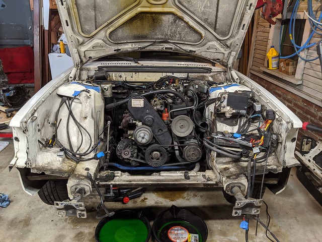
I took the whole fuel rail off because I couldn't get the flare nut loose on in, not even with two large crescent wrenches. I also got all of the wiring and hose loose so I should be able to work on lifting it out of the engine bay right away tomorrow.
The engine bay on this thing has always been pretty dirty:
A couple of hours (and dealing with a rounded off bumper nut) later, I had this:
I'd never pulled the front clip on a 240 before, so I found a Youtube video which was helpful, except for telling me that the nuts were 17mm. They're actually 16mm kids, and I happened to start on one that was already a little borked.
I ended finishing up around 10pm, this was the last pic I took though I got a little further:
I took the whole fuel rail off because I couldn't get the flare nut loose on in, not even with two large crescent wrenches. I also got all of the wiring and hose loose so I should be able to work on lifting it out of the engine bay right away tomorrow.
Last edited:
Broke4speed
Well-known member
- Joined
- Oct 5, 2009
- Location
- Marionville, Ontario, Canada
Huzzah progress! 
thatcher.hubbard
New member
- Joined
- Aug 21, 2013
- Location
- Seattle
It was a long weekend, was in the garage till 10 a couple of nights, but the engine is in the car. It's not quite ready to stay there permanently, but it fits and I'm happy with the motor mount clearance on the driver's side.
Getting the old B230 out took a little more doing that I would have thought, ended up taking most of the morning on Saturday, but it eventually came out:

As I said before, the engine bay was really nasty, especially down between the cross member and the steering rack. We got after it with some purple degreaser, a brush and a power washer and things are clean enough for me to live with:

A friend of mine is a former professional welder, he tacked the Homer mounts up for me on Saturday afternoon and then did the full job on them today after we'd test fit the engine into the bay. They do *require* some grinding/cutting on the back end of the driver's side mount so the steering u-joint bolt will clear, and in the case of my '92 with ABS, also required a tiny bevel on the back edge towards the outside of the car to clear the brake lines as they run along the frame rail. However, they were perfect in terms of the other dimensions and the engine basically sat right down in them with no drama:

It's not clear in the picture, but the transmission is on the back of the motor there. I need to tilt the driver's side mount ever so slightly in towards the center line of the car, mark and drill holes for the inner engine mount bolts in the cross member, then pull everything out so I can prime and paint the mounts.
There is a ton left to do, but just knowing I can get the engine into the car properly is a load off, and a lot of this is stuff I can pick away at a few hours at time.
Getting the old B230 out took a little more doing that I would have thought, ended up taking most of the morning on Saturday, but it eventually came out:
As I said before, the engine bay was really nasty, especially down between the cross member and the steering rack. We got after it with some purple degreaser, a brush and a power washer and things are clean enough for me to live with:
A friend of mine is a former professional welder, he tacked the Homer mounts up for me on Saturday afternoon and then did the full job on them today after we'd test fit the engine into the bay. They do *require* some grinding/cutting on the back end of the driver's side mount so the steering u-joint bolt will clear, and in the case of my '92 with ABS, also required a tiny bevel on the back edge towards the outside of the car to clear the brake lines as they run along the frame rail. However, they were perfect in terms of the other dimensions and the engine basically sat right down in them with no drama:
It's not clear in the picture, but the transmission is on the back of the motor there. I need to tilt the driver's side mount ever so slightly in towards the center line of the car, mark and drill holes for the inner engine mount bolts in the cross member, then pull everything out so I can prime and paint the mounts.
There is a ton left to do, but just knowing I can get the engine into the car properly is a load off, and a lot of this is stuff I can pick away at a few hours at time.
thatcher.hubbard
New member
- Joined
- Aug 21, 2013
- Location
- Seattle
I've been making slow progress on this because I've had to take it easy due to a bruised rib. I'd been working on getting the interior disassembled and figuring out the what and where of a supplementary fuse/relay panel in the interim. I also manage to snap this off of Craigslist for $500:

It's a Hobart 210 MVP, which ticked all of my boxes:
It even came with the spool gun for aluminum!
This will make solving the questions of exhaust and a transmission mount a lot easier to handle on my own.
I felt good enough today to get after finalizing the location of the engine mounts and I'm kind of stumped. It seems safe to assume that the center of the crankshaft should measure out at the same distance to either frame rail. Mine is off by 4-6mm towards the driver's side of the car. I've adjusted the passenger side mount towards the rail about as far as it can go, but it hasn't helped, so I assume it's the driver's side mount. I've already ground a fair amount off the back of that mount to clear the lower u-joint on the steering column, what appears to be about as much as other people using the Homer mounts have done. I may have to relieve it even more and maybe weld another reinforcing plate inside the mount when I've got it to fit.
It's a Hobart 210 MVP, which ticked all of my boxes:
- 120V and 240V input
- Came with a bottle (but it's argon)
- American-made so my welder friends don't give me any more sh*t
It even came with the spool gun for aluminum!
This will make solving the questions of exhaust and a transmission mount a lot easier to handle on my own.
I felt good enough today to get after finalizing the location of the engine mounts and I'm kind of stumped. It seems safe to assume that the center of the crankshaft should measure out at the same distance to either frame rail. Mine is off by 4-6mm towards the driver's side of the car. I've adjusted the passenger side mount towards the rail about as far as it can go, but it hasn't helped, so I assume it's the driver's side mount. I've already ground a fair amount off the back of that mount to clear the lower u-joint on the steering column, what appears to be about as much as other people using the Homer mounts have done. I may have to relieve it even more and maybe weld another reinforcing plate inside the mount when I've got it to fit.
thatcher.hubbard
New member
- Joined
- Aug 21, 2013
- Location
- Seattle
The question of centering the engine in the bay got sorted out with just a tiny bit more grinding, less than I'd feared. I was able to drill the inner mounting hole on each from the front, but I need to find a stubby 1/2" bit to get into the back, the distance between the cross member and the rear control arm mount is just a little too tight for my drill. Engine mounts got a bit of flap wheeling, self-etching primer and a couple of coats of paint, so they're ready to go in permanently:

Earlier in the thread I was trying to find a fitting to attach to the OEM fuel pressure regulator and was talking about it looking like a 5/8"-18 SAE thread. That was wrong. It's a 16mm, and if for some reason you want to hook onto one and convert it to -AN, this is your part:

It's a 16mmx1.5mm o-ring (or inverse flare) female to 6AN male. It was out-of-stock with the usual suspects (Jegs, Summit), so I ended up getting it off of eBay. I already had gotten a 6AN to 5/16" barb fitting, the combination of the two should make it possible to adapt to the OEM 240 fuel lines.
I also finished getting the dashboard out of the car. Removing the dash has always resulted in some interesting findings with my previous project cars, and this one was no different. There is like an entire lawn and garden bag's full of pine needles and leaves stuffed behind the heater core:

Nasty, but at least they're all bone dry. Somebody also did a hack job on getting the aftermarket stereo installed that included deciding that the best way to secure a bracket to the dash was to use a friggin' drywall screw, which made getting the stereo out quite a chore.
Earlier in the thread I was trying to find a fitting to attach to the OEM fuel pressure regulator and was talking about it looking like a 5/8"-18 SAE thread. That was wrong. It's a 16mm, and if for some reason you want to hook onto one and convert it to -AN, this is your part:
It's a 16mmx1.5mm o-ring (or inverse flare) female to 6AN male. It was out-of-stock with the usual suspects (Jegs, Summit), so I ended up getting it off of eBay. I already had gotten a 6AN to 5/16" barb fitting, the combination of the two should make it possible to adapt to the OEM 240 fuel lines.
I also finished getting the dashboard out of the car. Removing the dash has always resulted in some interesting findings with my previous project cars, and this one was no different. There is like an entire lawn and garden bag's full of pine needles and leaves stuffed behind the heater core:
Nasty, but at least they're all bone dry. Somebody also did a hack job on getting the aftermarket stereo installed that included deciding that the best way to secure a bracket to the dash was to use a friggin' drywall screw, which made getting the stereo out quite a chore.
thatcher.hubbard
New member
- Joined
- Aug 21, 2013
- Location
- Seattle
I have actually made some tentative progress on this project, though not a lot of it is picture-worthy and thus I haven't been posting.
I'll summarize as best as I can:
- The head is back on the engine and it's been timed:

- I have unwired the engine bay as far as I believe I need to at this point, and can start adding things back, starting with the use of the S90 main fusebox which I'll locate between the driver's strut tower and the ABS unit:


- I've got the dash/center console/heater unit mostly removed:

- I found an ordered the terminals I need to wire all of the new and existing power draws into the main fusebox once I have it mounted:

- I finished separating out what I need to retain from the S90 ECU/TCU harness:

- I trimmed the ECU tray from the S90 down so I can mount it to an ABS panel in the passenger footwell:

And finally, in a stunning display of doing a thing I said I wasn't going to do, I bought this of Craigslist for $100:

I had decided a couple of months ago that the effort to retain the AW30-40 with the TCU didn't make sense anymore because this is now my third vehicle and thus I can make it a manual if I want. At that point, my plan was T5 all the way, but they ended up being harder to find and more expensive than I wanted for something that a few people I trust said would feel "Meh".
Hence the Toyota W55. The ratios actually make good sense to me in a 3000lb. car with ~180hp. There are a couple of choices for adapters, and I already got my hands on a manual pedal box and a whiteblock single-mass flywheel.
I'll summarize as best as I can:
- The head is back on the engine and it's been timed:
- I have unwired the engine bay as far as I believe I need to at this point, and can start adding things back, starting with the use of the S90 main fusebox which I'll locate between the driver's strut tower and the ABS unit:
- I've got the dash/center console/heater unit mostly removed:
- I found an ordered the terminals I need to wire all of the new and existing power draws into the main fusebox once I have it mounted:
- I finished separating out what I need to retain from the S90 ECU/TCU harness:
- I trimmed the ECU tray from the S90 down so I can mount it to an ABS panel in the passenger footwell:
And finally, in a stunning display of doing a thing I said I wasn't going to do, I bought this of Craigslist for $100:
I had decided a couple of months ago that the effort to retain the AW30-40 with the TCU didn't make sense anymore because this is now my third vehicle and thus I can make it a manual if I want. At that point, my plan was T5 all the way, but they ended up being harder to find and more expensive than I wanted for something that a few people I trust said would feel "Meh".
Hence the Toyota W55. The ratios actually make good sense to me in a 3000lb. car with ~180hp. There are a couple of choices for adapters, and I already got my hands on a manual pedal box and a whiteblock single-mass flywheel.
swedishiron.com
I sell Volvo parts!
- Joined
- Mar 29, 2004
- Location
- Seattle, WA
And finally, in a stunning display of doing a thing I said I wasn't going to do, I bought this of Craigslist for $100:
(picture)
I had decided a couple of months ago that the effort to retain the AW30-40 with the TCU didn't make sense anymore because this is now my third vehicle and thus I can make it a manual if I want. At that point, my plan was T5 all the way, but they ended up being harder to find and more expensive than I wanted for something that a few people I trust said would feel "Meh".
Hence the Toyota W55. The ratios actually make good sense to me in a 3000lb. car with ~180hp. There are a couple of choices for adapters, and I already got my hands on a manual pedal box and a whiteblock single-mass flywheel.
I'm guessing you don't need me to keep my eyes peeled for a T5 anymore, then?
thatcher.hubbard
New member
- Joined
- Aug 21, 2013
- Location
- Seattle
More visually underwhelming progress has been made. In terms of "things that are hard", I got the heater box out, and that job has definitely earned its reputation, what a pain in the @$$. Mine was made a little more difficult by the fact that I could not get the driver's side fan wheel to come off the shaft, and ended up taking the whole thing out as one piece.

Which makes it possible to get the driver's side firewall panel out so I can weld up the old hole for the LH 2.4 wiring harness as well as cut off the EZK mounting hardware that is going to interfere with mounting the M4.4 ECU.
Not the easiest way to get access to your cam sensor...

I had bought and ABS panel to mount the ECU and my power distribution block to and was able to get it fitted using the two original holes the LH 2.4 used in the passenger's kick panel sheet metal. This should give me enough clearance to connect/disconnect the harness, and leave me enough room for the PDM on the bottom, though it is going to be a bit tight.

Which makes it possible to get the driver's side firewall panel out so I can weld up the old hole for the LH 2.4 wiring harness as well as cut off the EZK mounting hardware that is going to interfere with mounting the M4.4 ECU.
Not the easiest way to get access to your cam sensor...
I had bought and ABS panel to mount the ECU and my power distribution block to and was able to get it fitted using the two original holes the LH 2.4 used in the passenger's kick panel sheet metal. This should give me enough clearance to connect/disconnect the harness, and leave me enough room for the PDM on the bottom, though it is going to be a bit tight.
thatcher.hubbard
New member
- Joined
- Aug 21, 2013
- Location
- Seattle
Used some neoprene washers and got the right length stainless screws so I can mount the ECU up in what should be it's final location:

Also got the initial power run to the PDM crimped on and hooked up. I need to pigtail this wire so I have a couple of smaller wires to run to the 5A fuse for the ECU itself (always on) and the solenoid supply for the FI relay. The wire itself is just slightly smaller than a 10ga and was harvested from the donor car. It fits nicely through the rubber grommet in the firewall panel that the ABS harness comes through.

No pics, but I also crimped the correct terminals onto the "30" and "15" feeds that originally came from the weird little distribution block on the 240 driver side fender near the headlight step relay and then got them wired into the S90 fusebox.
I've been debating about how to proceed with the main ECU to engine bay harness. It seems like for purposes of practicality and avoiding issues with signal interference it can make good sense to split the cam and crank position sensors out. Volvo used twisted sets of wires to reduce crosstalk rather than the shielded solution that most aftermarket ECUs seem to recommend and that I've used before.
I have a 55-pin firewall connector that I was inspired to use by the Homer and Buchka swaps, but it's big enough that it may not fit well or even at all on the driver side firewall panel, and I've already got a big hole for the old LH2.4 harness in the passenger side. I guess I could make another, smaller hole for the signal wires and just keep everything on the passenger side. I also have a smaller 10-pin firewall connector I could use for those as well. By ditching the automatic and TCU my need for pin counts has gone down pretty significantly.
Also got the initial power run to the PDM crimped on and hooked up. I need to pigtail this wire so I have a couple of smaller wires to run to the 5A fuse for the ECU itself (always on) and the solenoid supply for the FI relay. The wire itself is just slightly smaller than a 10ga and was harvested from the donor car. It fits nicely through the rubber grommet in the firewall panel that the ABS harness comes through.
No pics, but I also crimped the correct terminals onto the "30" and "15" feeds that originally came from the weird little distribution block on the 240 driver side fender near the headlight step relay and then got them wired into the S90 fusebox.
I've been debating about how to proceed with the main ECU to engine bay harness. It seems like for purposes of practicality and avoiding issues with signal interference it can make good sense to split the cam and crank position sensors out. Volvo used twisted sets of wires to reduce crosstalk rather than the shielded solution that most aftermarket ECUs seem to recommend and that I've used before.
I have a 55-pin firewall connector that I was inspired to use by the Homer and Buchka swaps, but it's big enough that it may not fit well or even at all on the driver side firewall panel, and I've already got a big hole for the old LH2.4 harness in the passenger side. I guess I could make another, smaller hole for the signal wires and just keep everything on the passenger side. I also have a smaller 10-pin firewall connector I could use for those as well. By ditching the automatic and TCU my need for pin counts has gone down pretty significantly.