• Hello Guest, welcome to the initial stages of our new platform!
    You can find some additional information about where we are in the process of migrating the board and setting up our new software here

    Thank you for being a part of our community!

Wasted spark v/s direct fire?

per0lund

Member
Joined
Feb 29, 2004
Location
Stockholm Sweden
I?m in to upgrading the wasted spark coil pack in to direct fire
.
In my mind a wasted spark is right what it says, wasted energy that probably could be better used.
I have four small standard E-core coils suited for most stock electronic four cylinder distributor ignition systems, with a primary resistance of 0,8 ohms, and the DiYAtotune quad spark ignition module.
The coils should each deliver 36000 volt@2000 sparks/min if fed with enough power.

It may bee the quad spark module is more suited for coils with 0,4 ohm primary resistance, but I?m just not shure how the quad spark module will work with higher resistance
I?m not experienced in direct fire systems, but if these coils work, I believe they still would be more efficient than the Bosch Motorsport coil pack (0,4 ohm at primary).
If it works it will be a very low budget direct fire system as these coils are only 18 U.S $ each

I haven?t checked out whether I need a extra camshaft sensor ,or if the software of MS3X V3.57 can use only the stock crank signal for direct fire.

I got a feeling someone else has tried this concept before me.

And I do not expect a great difference, but never the less it may still be a small improvement of engine efficiency, at a fairly decent cost.
 
If all you want to do is get rid of the double ended coil you don't need a cam sensor. You can still do the wasted spark trigger and firing arrangement; but, use an individual coil on plug (kind of difficult on a B230) or coil near plug arrangement on each sparkplug. I don't know the specifics of MS3. You might need an extra TC427 driver chip to provide 4 logic level ignition outputs. With the wasted spark arrangement you just fire two coils at the same time as opposed to sequential which requires the cam position signal.
 
If all you want to do is get rid of the double ended coil you don't need a cam sensor. You can still do the wasted spark trigger and firing arrangement; but, use an individual coil on plug (kind of difficult on a B230) or coil near plug arrangement on each sparkplug. I don't know the specifics of MS3. You might need an extra TC427 driver chip to provide 4 logic level ignition outputs. With the wasted spark arrangement you just fire two coils at the same time as opposed to sequential which requires the cam position signal.

I already have a DiyAutotune QuadSpark Ignition Module, and thought that would be enough, without having any extra TC427 driver chip.
 
If the MS3 has 4 (or more) logic level ignition outputs, then you are correct that you do not need an additional TC427 if you are running full sequential ignition; but that requires a cam trigger.

If you don't want to add the cam trigger and are prepared to retain the wasted spark triggering configuration; but, fire two coils at once , then if the MS3 software allows you to run wasted spark and reconfigure two existing logic level outputs to fire at the same time, you don't need a TC 427. You might be able to pair up two inputs to your quadspark and run them directly off of one logic output from the MS3 without a separate TC 427 driver. That would require that whatever the MS3 uses as a driver have enough current capability to drive two inputs on the quadspark at the same time. Without dissecting the MS3 to figure out its schematic, I would not risk that.

Perhaps its just easier for you to figure out a cam trigger and go full sequential rather than risk modifying the MS3.
 
I haven?t checked out whether I need a extra camshaft sensor ,or if the software of MS3X V3.57 can use only the stock crank signal for direct fire.
This just doesn't work conceptually. It's a 4 stroke engine, the crank makes two complete rotations between each individual cylinder firing.

With only a crank signal, the ECU has no way to tell where in the cycle a given cylinder is, Nearing TDC on the compression stroke (need to fire that spark!) or nearing TDC on the exhaust stroke. Wasted spark setups just don't care, and they'll fire the spark in both situations, because it doesn't really hurt much of anything to fire a spark at the outgoing exhaust gasses.

To allow the ECU to tell the difference between the compression stroke and the exhaust stroke, you need a cam sensor. The cam turns at half the speed of the crank, so it can tell the ECU which phase a cylinder is in, compression or exhaust. And the ECU can only fire the spark when it needs to.

Yoshifab makes a nice adapter to run a DSM engine sensor in the block mounted distributor spot. This has both sensors in it - crank and cam. One sensor 4 wires, works great. It's a powered sensor too, so it sends nice clear 5V ON and OFF signals to the ECU, not those squirrelly variable voltage blips that the ECU has to make sense of that the stock flywheel sensor sends.
 
Also, what Lord Athlon said. It's a learning curve, but you'll be better off understanding what all the sensors are doing, and why.
 
Well I expected a cam position sensor would be necessary, I plan to use one from the B-230GLE <-88 (in distributor).
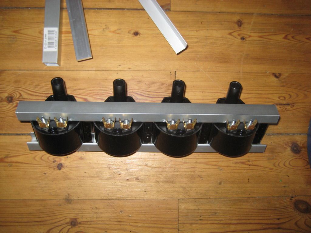
This is a pic of the coils, larger than normal direct fire coils but not that large. I will make a "sort of" coilpack of my own.
 
Am I reading this right? You want to replace a wasted spark system.... with a wasted spark system?

Hardly, four coils a quad channel ignition module/amplifier, a cam position sensor, and a crank position sensor wouldn?t really be needed for wasted spark ignition.

I?m more in to a sequential ignition or direct fire.
 
Hardly, four coils a quad channel ignition module/amplifier, a cam position sensor, and a crank position sensor wouldn?t really be needed for wasted spark ignition.

I?m more in to a sequential ignition or direct fire.

Guess I'm confused as to the point of this thread since this topic has been covered and executed hundreds of times.

X3 RTFM
 
The quad ignition module came without a complete documentation, I don?t find all specs about it.

If you go to the DIYAutotune website and look under Products / Ignition you will find your module. On that page there is a documentation link which covers connection of the module to the various versions of MS and the coils. Arranging for a cam position signal is a separate matter.
 
If you go to the DIYAutotune website and look under Products / Ignition you will find your module. On that page there is a documentation link which covers connection of the module to the various versions of MS and the coils. Arranging for a cam position signal is a separate matter.

Yes I did, but wiring isn?t my worry, question is rather can this module operate these slightly higher primary impedance/resistance coils 0,8 ohm well. They won`t run hot in first place that's fore shure.

As I understood it?s most common to run 0,4 ohm HVC coils like the Bosch Motorsport wasted spark coil pack, or IGN-1 Inductive Coil.

I already have a extra distributor from a B-230E -85 engine with a hall sensor, I can use for cam signal. I don't se a problem in that.
 
If the DIYAutotune ignition module is based upon the Bosch BIP 373 driver, there may not be a point to a really low resistance coil. Do a search on 'Bosch BIP 373 datasheet' and you will find that the BIP 373 has an internal current limiting feature. The typical value is limiting at 12 amps. The maximum limiting value is 16 amps. The Vce sat value of the BIP is around 2 volts. If your car is running around 14 volts, the net voltage to the coil is around 14- 2 = 12 volts. With a 0.4 ohm coil resistance that would translate to a peak coil current of 30 amps with no current limiting and unlimited dwell. Clearly the BIP will limit current before it hits that value. With a 0.8 ohm coil resistance the peak coil current with no limiting and unlimited dwell will be 15 amps, so the BIP may or may not enter current limiting.

Because of the self protection built into the BIP 373, it should be able to handle either a 0.4 or 0.8 ohm coil without risk of damage to the BIP (assuming that it is properly mounted on a heat sink surface). The more important question will be what is the repeated current limit on your 0.8 ohm coils. The 12 - 16 amp limit in the BIP may be beyond the limit of the coil if you do something really silly with your dwell time. Find out what the dwell limit is for your coil, respect that limit in the ignition settings and the BIP 373 won't present any issues for you.
Thank you that is what I wanted to know.

I don?t have all data for these coils all I know is Primary resistance 0,8 ohm inductance 5,6 mH,
Secondary is 1,1 KOhm and 30H.
 
Last edited:
If you go to the MS Megamanual ignition section (B&G, not MSExtra), they provide a discussion and an analytical model for calculating the spark energies from a coil based upon the coil resistance, inductance, charging voltage and dwell time. I think they also link or you can find references on the web that discuss the spark energy required for reliable ignition. You already have the resistance and inductance and should have a reasonable value for your coil charging voltage. Once you find the range of spark energies required to achieve reliable ignition, you should be able to use the B&G analytical model to calculate what is a reasonable maximum dwell that you should be using for your coil. The B&G model is not perfect; but, it should provide you with a good starting point for estimating dwell if the coil vendor does not specify a maximum dwell and maximum primary current.
 
Back
Top