Your dudular Dudeness, for us humle schmucks who want to try and understand can you give us a simple sketch of impressions--your considered impression being worth more than 10,000 20 year olds who heart their whatever that duct taped on--- on the say 7 blade things like these:
T3 7 blades
441341-0002 ..........69,00 47,65 4,75 6,25 46
431905-0004 ............69,00 48,25 5,60 6,25 48
410299-0004 .............69,00 52,50 6,25 58
Or some general "given this major dia and thhis tip hgt, I would expect a 7 blade wheel to_____________in comparison to a _ ___blade wheel of same basic dimensions"
Shirley there's some reason
I just did several searches, but these are all so old that I cannot find performance maps in our systems for any of the above wheels. They were designed in 1978-79 which I know wasn't the dark ages but is prehistoric in terms of compressor aero.
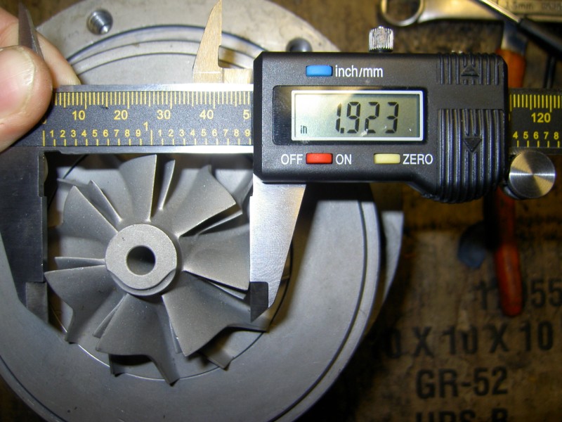
441341-0002 is a "7+7" blade wheel; 7 full blades and 7 splitters (the short stubby ones) for 14 total. Exducer diameter is 68.92mm, inducer is 48.79, trim = 50, and blade tip width is ~4.9mm. Versus a similar wheel with only 7 full blades, this would impart more energy to the flow via splitters, giving higher pressure ratio capability. 14 full blades would tend to reduce flow area enough to limit flow range significantly, especially with these old thick blades. Looks like it has some backwards curvature which will provide greater flow range, moving the surge line to the left vs. a purely radial blade root. It will also cause peak efficiency to occur at a higher flow rate, towards the choke side.
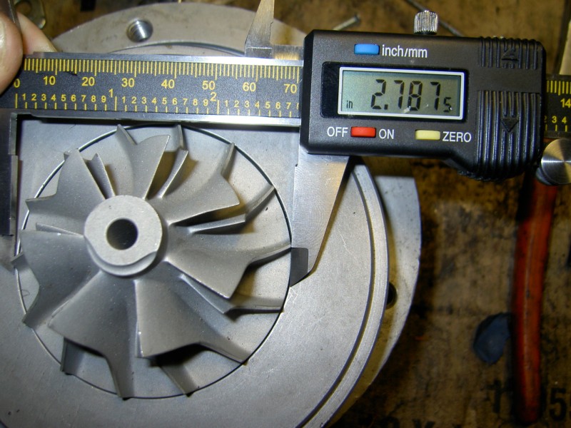
431905-0004 is another 7+7 wheel, with a slightly larger exducer at 69.98; inducer is 49.53, meaning this is also a 50-trim wheel. Tip width appears to be wider on this one which would match your values given above but it's not explicitly called out so I can't verify.
Wider tip width increases the exit flow area and therefore reduces relative exit velocity. This improves efficiency at lower pressure ratios, i.e. it moves the peak efficiency island downwards on the map. It may also increase peak efficiency since there will be less pressure loss occuring in the wheel. This wheel would be better optimized for a low-boost application. Can't say how much lower since I can't find any maps, but qualitatively anyway.
410299-0004 is again 7+7 and appears similar to 441341-0004, except for the larger 53.47mm inducer making it a 60-trim wheel. This shifts the entire flow range to the right on the map, by a factor of 60/50 (new trim/old trim) = 1.2. Tip width does appear to be wider still, near 6mm. This would be the best of the three for a higher flowing, low boost application.
Low flow / high boost would be best suited to 441341-0002, including high altitude use (therefore high pressure ratio even if boost gage pressure in the manifold is "low").
Somewhere in between would be 431905-0004.
Hope this helps!

") -P), with the Ford cartridge you need to use banjo bolts in m18x1.5. I can't find the pics of how I did it, just drilled the holes in the Volvo line banjo's from 16 to 18 mm with a stepped drill and used M18 bano bolts..
-P), with the Ford cartridge you need to use banjo bolts in m18x1.5. I can't find the pics of how I did it, just drilled the holes in the Volvo line banjo's from 16 to 18 mm with a stepped drill and used M18 bano bolts..