• Hello Guest, welcome to the initial stages of our new platform!
    You can find some additional information about where we are in the process of migrating the board and setting up our new software here

    Thank you for being a part of our community!

Fuel/Spark tuning for LH 2.4/EZK with TunerPro!

If I remember correct the bin is 4kb. 27c32 is the chip and 24pin.
But how come i can read the file from ostrich and it show up just like when i read the chip? I have the 28 pins from ostrich pluged in to the Socket booster and The Socket booster plugged to the eprom reader with 4 pins off at the notch side and set to 24pin on the switch it shows the full bin just like with the chip.
But when i plug the socket booster/ostrich setup with 4 pins off to the ecu the car won't start..

Reading the file from ostrich has nothing to do how ECU is reading it. You read it through
the USB and the ECU is reading it through the emulated chip pins. It is emulated dual port memory. Also since the memory inside ostrich is segmented the binary might be offset differently when read by the ECU.
I guess you has read this: http://support.moates.net/ostrich-20-overview/
You can try adjusting bin size to 0x1000 (that is 4096 in hexadecimal) or playing with the bin offset in 4K multiples. Another option is to try to concatenate your bin file 16 times, so that it becomes 64K image and upload it to ostrich and see if it works. A segment (or bank) in ostrich is 64K. I think you can use bin stacker option in tuner pro, google it or see this:
http://support.moates.net/2timer. If it starts like this you can use address tracing to find out which 4K copy is used by the ECU

I think you missunderstud me sorry, if i put the ribbon cable (chip end) to a eprom reader and open the minipro program and read the chip (ostrich) it shows up just like if my original chip was plugged in. Im not read ingen the ostrich trough a usb But i will try youre advise thanks
 
Hi. When i connect the ostrich cable chip end to my eprom burner/reader and try to read it it says overcurrent protection and won't read the ostrich. Bit if i the connect the ostrich to my computer with the usb cable and try to read it with the eprom burner/reader it shows up just fine.. so maybe there is some voltage problem with the ostrich and that why the car won't start? When emulating LH it works just fine but not with motronic.
Regards Dudde
 
Anyone using the J723T power stage with the WSB find a replacement # for the 6 pole connector? The one I have is damaged. Not having much luck searching for this :( The 3 pole can be replaced with a regular Bosch connector, so that one is no problem.
 
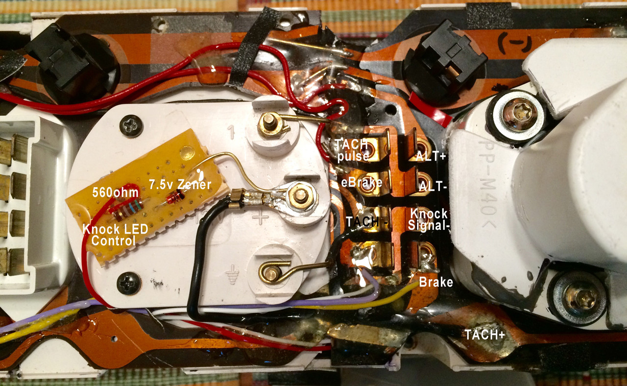
You need 7,5v zener diode, 560 ohm resistor and RED led.

Connect it to some where switchable 12v (i've put mine to meter lightning) and connect so called VSS side to grey/red wire what goes EZK to LH (knocking enrichment triggering, pin 4 in EZK and pin 28 in LH).
I took +12V in meter panel over heat light (not in use FT-engine) and connect behind meter panel Grey-red wire.


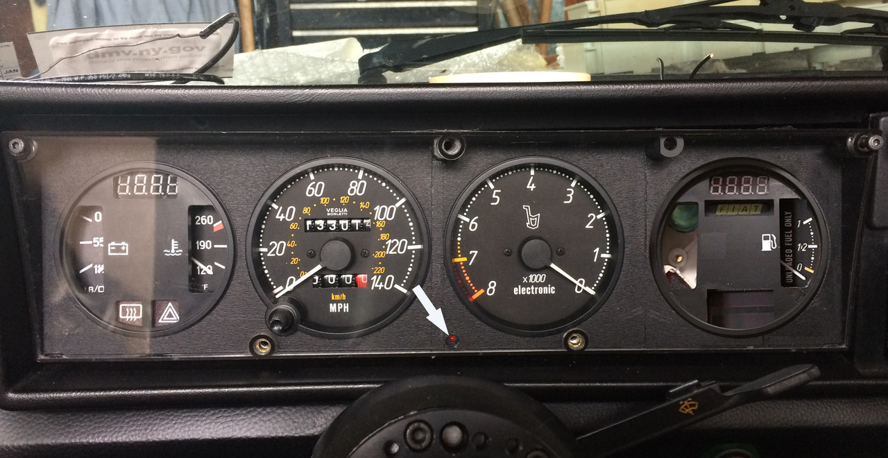
Finally got this set up: added circuit to back of instrument cluster

X19-0118j.jpg


Led in lower center

X19-0116m.jpg
 
Last edited:
Hi!

A question for gurus about communicating with LH: I have connected a USB-to-TTL converter (based on Prolific PL2303 chip) to LH's tx/rx lines, cut the traces. Reference GND is also present.

I have Ostrich to emulate ROM, I've tried the serial communication with numerous of different bins, but no luck. Serial debug flag enabled and I'm pretty sure I also have the settings correct: 187500 baud, 8 bits, space parity (to read internal ram)? Originally ecu is 936, from a N/A b230 940, I think.

I'm using Windows 10 and Realterm if that matters. Tried sending bare numbers (hex/bin) and ascii, but all I can get in return from LH is null bytes eg. 0x00, is this supposed to happen?

Using old LH-logger bins from Beepee I can get some serial data from LH (which proves the connection kinda works), but without the source code of any programs my understanding of the data is very limited. Ramread or lh-logger doesn't work for me, which I frankly don't care about because I was going to code my own software....


E: It seems like I messed something up with the 8 databits and parity -setup, even though I tried with different parity settings. I compiled 950 bin from ASM with the MOVX (external ram read) changed to "MOV", and at least now ecu responses with something different than 0x00. I think it tried to read the external ram which isn't even attached...


If you did right everything as explained here: http://ipdown.net/wiki/index.php/LH_2.4_Jetronic#Datalogging_with_LH2.4
all you need to communicate is to enable serial debug flag. Serial settings are:
187500, 1 start bit, 1 stop bit, 8 data bits, space or mark parity - space parity to read internal ram, mark parity to read ext. ram. Make sure you connected TX/RX lines properly, e.g. LH TX to USB RX, and LH RX to USB TX..
What language you are using to code your program? I can give you examples for python and MSVC++.
 
Hi! I think my serial software (Realterm) or something bugged things up. I tried swapping tx/rx, but no help. I could only receive 0x00. I changed the asm source to read only internal ram, even with mark parity and now the ecu responds as it should. This means the ecu was trying, for some unknown reason, to read the external ram which doesn't even exist in -936 box, hence the 0x00 response.

I'd very much like some Python examples, because thats the language I was going to code the final logger software. I was thinking of adding wideband output to some of the unused ADCs and implement some kind of "autotune" feature eventually. :oogle:
 
A little update about datalogging / RAM.

I coded a dirty read-all-ram -program in Python, seems to work. Using a 950 bin compiled from scratch (ipdown's / beepees source, thanks!)

However the known addresses for specific values like RPM, coolant temp etc. doesn't match up.

0x31, which is supposed to be the time between pulses (from which we can calculate RPM), starts from 0xFF/255 at ~1000RPM and gradually lowers when the revs go up.
Completely logical, BUT... Around 0xB0/176 the value suddenly jumps to 0x8F/143, messing the calculations up. It's feels like the ecu is avoiding 0xAX and 0x9X values perfectly.

0x55, which is supposed to be coolant temp in some form, stays constant at 0x00.

Did I break the whole code by changing a MOVX to MOV? At least the car still runs "fine". :lol:
The change was done on the serial debug routine, to prevent ecu from reading ext_ram (which still doesn't even physically exist).
I can't read the internal ram without the change, no idea why. Everything is just 0x00 without tinkering the ROM.


As I said, you don't need to change code if you are connected directly. Only enable serial debug flag - that can be done on a bin file with TunerPro.

Assuming you are using pyserial - the standard python way for accessing serial port you need to do something like this to read (internal) RAM:
HTML:
import serial
import math

def read_RAM(ser, address):
   ser.write(address)
   return ser.read(1)

def read_RPM(ser):
    raw_val = read_RAM(ser, 0x31)
    return (5e5*30) / (math.pow(2, ((raw_val + 128) / 32)) * 64)

def read_eng_speed(ser):
    raw_val = read_RAM(ser, 0x43)
    divider = 16
    return 5e5 / (((37500. / raw_val) * divider) / 30.)

def read_temperature_C(ser): # in Celsius degrees
    x = read_RAM(ser, 0x55)
    a,b,c,d,e,f = 1.57e+2, -4.54, 7.59e-2, -6.64e-4, 2.75e-6, -4.32e-9    
    temp = a+b*x+c*math.pow(x,2)+d*math.pow(x,3)+e*math.pow(x,4)+f*math.pow(x,5)
    return temp

def read_temperature_F(ser): # in Fahrenheit degrees
    return read_temperature_C(ser) * 9/5. + 32

def read_load(ser): # 0-100 %
    return read_RAM(ser, 0x4F) / 2.55

def read_battery_voltage(ser): # volts
    return read_RAM(ser, 0x59) * 0.0625

def read_lambda_corr_factor(ser): # range is (-1.0 : 1.0), around 0 is stoich
    raw_val = read_RAM(ser,0x4C) + read_RAM(ser,0x4D) * 256
    return (raw_val / 32768.0) - 1.0

def read_injector_PW(ser): # pulse width in ms
    raw_val = read_RAM(ser,0xBC) + read_RAM(ser,0xBD) * 256
    return raw_val * 0.002

if __name__ == '__main__':
    port_name = 'COM1' # whatever is your USB to COM converter
    ser = serial.Serial(port_name, 178500, parity = serial.SPACE_PARITY)

    
    rpm_raw = read_RAM(0x31) 
    load_raw = read_RAM(0x4F)

    rpm = read_RPM(ser)
    pw = read_injector_PW(ser)
    # ... do whaterver you want..

    ser.close()
 
Last edited:
Tried your code, no success. Changed baud rate btw, your code had 178500.

With the car running around 1200rpm, using standard 950 bin (debug enabled), printing your rpm_raw:
b'\x00'
b'\x00'
b'\x00'
b'\x00'
b'\x00'
b'\x00'

The above happens also with 937 bin, debug flag enabled.

With the car running around 1200rpm, using modified 950 bin:
b'\x0c'
b'\xfe'
b'\x0c'
b'\xb2'
b'\xf4'
b'\x7f'

Which still converts to some nonsense readings.

I'll keep on trying... :wtf:
 
Last edited:
It's the only bin I have source for. Tried to disassemble a 937 with various disassemblers, but can't get the source to compile.

Here is a short log of ram in dec values: https://www.youtube.com/watch?v=j_mLaOPDAIQ

EDIT: the last row seen in cmd is wrong. It actually read ram at 0x62 at the moment of capturing the video.


EDIT2: Seems like the serial to usb chip was the problem. I tried the LH-to-computer connection with Arduino hooked up as USB-to-serial converter and it just works. I think it has Atmega 16u2 acting as a basic ftdi chip. The Prolific PL2303 I previously used is doing something wrong, or I'm interpreting the output wrong.

Find FTDI converter, it works. Since that baud is non standard, that combined with weird parity might confuse pl chip. Or driver. Whatever.
Parity is actually not real parity bit, but 9th bit,
so the real settings are 1 start, 9 data bits, 1 stop bit. Since this is even more weird we use parity bit to emulate the 9th one - space is 0, mark is 1.
The 80c535 RAM is just 256 bytes it can be addressed with single 8 bit byte. The 9th bit just selects if MOV or MOVX is used (internal/external read) and the rest 8 bits are address to be read. The protocol is simple - you write a address byte, and read back its content. Pretty fast also, the only problem is when you read 16 or more bits values - the consecutive reads are not atomic and you can read bogus values. But 8 out of 10 reads succeed.
 
Thanks for the reply. I think Prolific drivers for Windows aren't the greatest comparing to what they could've done. And I need Windows to be able to run TunerPro, so the PL chip is now abandoned from this project.

I understand the protocol and that I should send 9 data bits. However I can't get any of my current chips to replicate the behaviour with the parity bit, hence I needed to change the MOVX to MOV. I've tried numerous combinations of parity and other settings. The problem is that I can't really properly check what actually is sended to the ecu processor, but it seems like the Atmel is doing a great job even with the strange baud rate. I still need the modded bin, but it's no problem for me because I don't even have the external ram chip fitted, so no need to read it.

I dont mind the speed, it's actually great to be able to read the whole ram in almost real time. I've thought making some changes to the source for reading the 12/16bit values correctly, but as of now I'm just focusing on fixing my current code and making a quick'n'dirty version of a simple logger.
 
Requirements for LH2.4 Vss Signal?

I have a question for the LH2.4 experts out there and this seems like the best place to post. What are the requirements for the Vss signal in firmware? Does this need to be 12 pulses per axle rev, as normally measured at the rear differential, or will other signal rates work just as well?

In other terms, does LH2.4 only care about stopped versus moving, or does it use the estimated speed for part of the control algorithms?

Electrically, the speedo chip in the 86+ cluster converts the VR pickup signal from the rear differential to an open-collector Vss output to the ECU. Within the LH2.4 ECU, it looks like there's a ~10K pullup resistor to +12v on the Vss input.

[I'm slowly rebuilding an engine for my '85 K-Jet wagon and would like the option to run LH2.4 off of the cruise control VR pickup in the pre-86 cable-driven speedo. I haven't yet figured out what the pulse rate is off the speedo and how that compares to the 12 pulses/rev from the normal differential sensor. I know I'll need a simple converter circuit for this if the pulse rate is OK for LH2.4.]

Edit: doing my own followup here:
I tested the cruise control pickup on a cable driven speedo. It generates 4 pulses per cable rev, ~680mV peak-to-peak amplitude with a 1K resistor across the pickup coil, and a ~35Hz rate at 30MPH. The standard 12 pulse/axle rev LH2.4 rate at 30MPH is ~81Hz, or roughly 2.3x faster. This is not a good match.

I also disassembled and traced some of the INT2 code used for Vss monitoring. The code includes both high range and low range Vss calculations, using tableized conversion factors. My best guess is that code needs 12pulses/axle rev to work correctly (or would need to be re-written for the much slower rate from a cable driven speedo).

-Bob
 
Last edited:
I have a question for the LH2.4 experts out there and this seems like the best place to post. What are the requirements for the Vss signal in firmware? Does this need to be 12 pulses per axle rev, as normally measured at the rear differential, or will other signal rates work just as well?

In other terms, does LH2.4 only care about stopped versus moving, or does it use the estimated speed for part of the control algorithms?

Electrically, the speedo chip in the 86+ cluster converts the VR pickup signal from the rear differential to an open-collector Vss output to the ECU. Within the LH2.4 ECU, it looks like there's a ~10K pullup resistor to +12v on the Vss input.

[I slowly rebuilding an engine for my '85 wagon and would like the option to run LH2.4 off of the cruise control VR pickup in the pre-86 cable-driven speedo. I haven't yet figured out what the pulse rate is off the speedo and how that compares to the 12 pulses/rev from the normal differential sensor. I know I'll need a simple converter circuit for this if the pulse rate is OK for LH2.4.]

Thanks,
Bob

Did your car come with cruise control? You may just be able to use cluster you have if it did. Another way is you can use abs struts and use the tone ring on that to feed the vss signal to lh.
 
Hi , maybe someone can advise me. I have 89' 740 B230f LH2.4 . Now i am making + T, and i have bought 984 fuel ecu and 148 ezk with injectors from same car - 98' 940 B230fk. this ecu is with imobilliser, and i have no start with it :) What Bin is best to use with this ecu? my setup is 16t turbo, T cam
 
Hi , maybe someone can advise me. I have 89' 740 B230f LH2.4 . Now i am making + T, and i have bought 984 fuel ecu and 148 ezk with injectors from same car - 98' 940 B230fk. this ecu is with imobilliser, and i have no start with it :) What Bin is best to use with this ecu? my setup is 16t turbo, T cam

954 works as that's what i'm using with my 148 bin EZK. got round my immo'd 977. I'm not sure if there's a 'best'. the later ECUs get more functions i think? There are some un-compatible combinations of Fuel and EZK bins.

The VSS, I know it's used for the shift light, and something to do with idle/decel. I ran a B200+T in my volvo 360 and just didn't hook up a VSS and it worked fine. ABS cars get a 48 tooth wheel, I've used the same ecu on my 12 tooth and not had any problems. A proper solution of course would be better, Interested to see what you come up with. Re-writing the code to suit the speedo signal you have would be the best way, if that's do-able.
 
Back
Top