• Hello Guest, welcome to the initial stages of our new platform!
    You can find some additional information about where we are in the process of migrating the board and setting up our new software here

    Thank you for being a part of our community!

Howto: Using the Volvo 240 speedo output to Speeduino (possibly other EFI as well)

Broke4speed

Well-known member
Joined
Oct 5, 2009
Location
Marionville, Ontario, Canada
I'm currently running Speeduino on my B6304S+T setup, and the latest firmware includes a VSS input. I decided to try incorporating the speed output from the 93 ABS cluster I'm using, since it seems to put out a 5v square wave.

Well, it does...but I'm not sure how clean it is because I cannot get a stable signal out of it for my Speeduino. I had originally done a bunch of stuff and got a great signal...but the voltage was too high and would have killed my ecu. That's a shame because it worked perfectly and the 'right' way doesn't :(.

Perhaps other people will have more success.
 
Last edited:
The speedo signal is an open collector output. If you don't have the stock ECU connected then the voltage should be whatever you pull it up to.
 
I pulled it up to 12v with a 330 ohm resistor, and it worked great...but on it's own it seems to put out 5v. It 'works' without a pullup, but it fluctuates madly. If I pull it to 5v using the VREF of the ecu, the result is the same. Could the UAF2115 chip require a 12v pullup on the signal because it's fed 12v initially?

Everything I could find about LH2.4's use of the speedo signal says that it's a 12v signal so there's obviously an internal pullup in the ecu somewhere. The issue is that the ecu I'm using (Speeduino, pre-built CORE4 module from DIY-EFI.co.uk) is not tolerant of 12v on the input I have to use. I have a voltage divider all made up, but I need to try it after the pullup to see if it works or not. This whole thing is getting a bit out of hand though, considering I don't even need to use the signal for anything other than 'just because it's there'.

The LH2.4 pinout/diagnostic shows that voltage should be either 0v or BatV, and that it should be 6-7v at any RPM higher than idle on pin 34. This is exactly what I saw when testing the signal with a 12v pullup and a true-RMS multimeter (not ideal, but fits the diagnostics). My problem basically stems from my chosen ecu not being able to handle the larger voltages for long.

tiki-download_file.php
 
The chip in the speedo that drives the VSS signal is a UAF2115 - try a google and rummage around a bit for a good pdf. Pin 3, the "taximeter" output, is an open-collector driver. It should work fine with a 330 pullup resistor to +5v. Do you have a scope to check the signal?

Does the Speeduino enable the weak internal Arduino input pin pullup resistors? Maybe that's what you're seeing for flakey 5v behavior without an external pullup resistor.

How do you like the Speeduino, or is it too early to know?
 
The chip in the speedo that drives the VSS signal is a UAF2115 - try a google and rummage around a bit for a good pdf. Pin 3, the "taximeter" output, is an open-collector driver. It should work fine with a 330 pullup resistor to +5v. Do you have a scope to check the signal?
Unfortunately no :(. The funny thing is that it shows 5v without any pullups, and when I tried a 330 to VREF, the voltage stayed the same...5v. It's a 1993 cluster from an ABS car with cruise control.

Does the Speeduino enable the weak internal Arduino input pin pullup resistors? Maybe that's what you're seeing for flakey 5v behavior without an external pullup resistor.
The input I'm using might have a pullup on it, since its for a flex fuel sensor and can take the signal straight in. I'm using a purpose-built board (CORE4 from diy-efi.co.uk) which only uses the Atmega chip from the arduino mega2650, so everything is designed for automotive use in this case. If there is a pullup on the circuit, that might DEFINITELY be the reason I'm seeing a 5v signal straight out of the cluster when connected to the Speeduino.

How do you like the Speeduino, or is it too early to know?
I like it. It's completely open-source, and while I'm definitely not a coder, I've had success with building a few of these for others. Using an Arduino Mega as a brain really brings the price down, so each unit can be built for ~$150 CAD. It's like Megasquirt back in the early days, but with more processing power than MS1 and all the features of MS2 natively onboard. No mods necessary. The firmware is growing by leaps and bounds and has been really stable for a while, so there's no abrupt re-tuning necessary when upgrading. My B6304 swap runs really nicely on it, with fewer issues than any MS setup I've had (although that may be experience-based results, not hardware). I like it :).
 
Can you post a link to the CORE4 schematics? It is open source, right? Or are folks already doing non-open knockoffs? Maybe the flex fuel input is for a 12v signal, or has some sort of additional filtering.
 
CORE4 is a commercial product made by DIY-EFI.co.uk, no schematics readily available, but it is mostly based on the latest 0.4.3 Speeduino PCB (https://github.com/noisymime/speeduino) I'd imagine.

Josh Stewart (Noisymime) is the guy behind all this, and he doesn't care what anybody does with the schematics :). I liked the CORE4 board simply because it's practically credit-card sized and I could make my own base PCB to mount it on to fit my needs. I have some assembled 0.4.3 speedy boards from official schematics (that I had made on my own), and the BOM is on the github :).

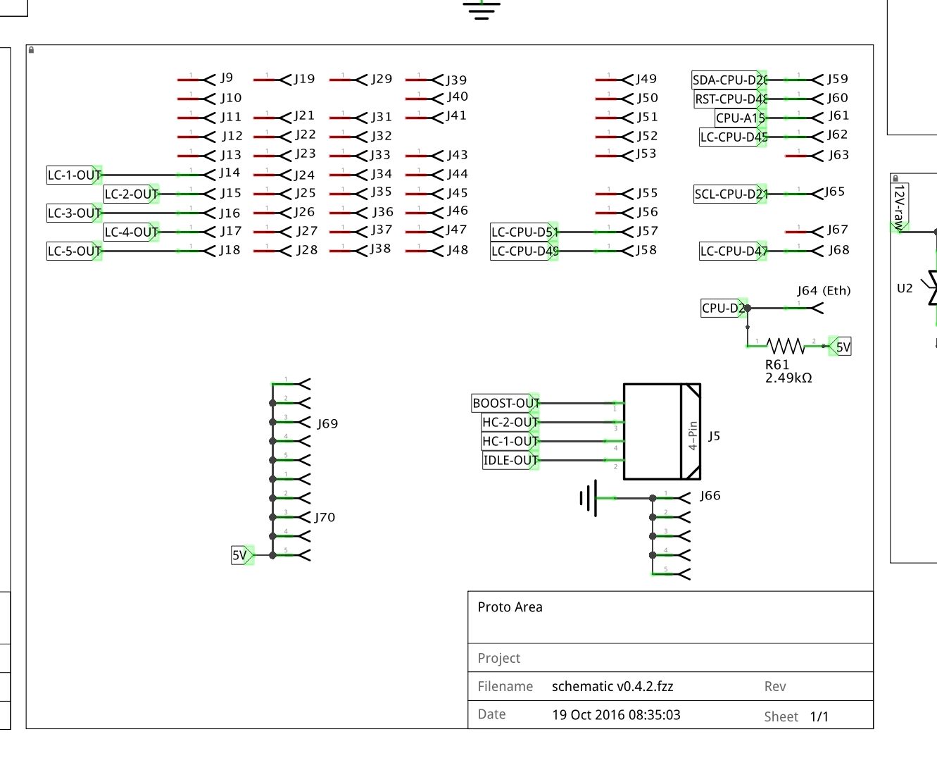
[edit]According to the official schematic, the Ethanol input (in the Proto Area of the standard 0.4.3 board) has a 2.49k Ohm pullup to 5v on it.

BThjGzv6_o.jpg
 
Last edited:
OK, you shouldn't need any external pullup if the CORE4 matches that ^^^ schematic.

If you're stopped, the VSS signal will be 5volts. Once you start moving, there will be brief pulses going down to ~0.2v. Pulse rate (frequency) range should be roughly 10Hz (barely moving) to 200Hz (75mph-ish). You'll need to configure, or code, the Speeduino to measure the pulse rate.

If you put a suitable LED and resistor across the VSS signal and +5v, you may be able to see it blink on each pulse (don't use an incandescent test light, it may draw too much power and damage the UAF2115 chip).
 
I'm definitely seeing 5v at idle, but the KPH display fluctuates even though I'm not moving. Now I think it's a firmware problem, because it looks like everything is fine on the vehicle end. There's a smoothing function, but it doesn't seem to do much. I should look in to that next. Thanks for the help!
 
You should definitely put a scope on the signal if you actually want to figure out what's going on. A multimeter isn't going to give you enough information.
 
I really think the problem is the input I'm using. There is a pullup already on the board, but I think the value is not proper for my needs. I may be grasping at straws, but tomorrow I'm just going to swap the input to the unused cam sensor port.

I have an old scope, but it's never been very reliable. I'm looking around to see if anyone has one I can borrow.

I don't see any obvious issue with a ~2.5k pullup. The input impedance of the micro is orders of magnitude higher than that. You might want to look at the code that samples the input and make sure it's doing sensible things.
 
I have an old scope, but it's never been very reliable. I'm looking around to see if anyone has one I can borrow.

For automotive stuff I have bought one of those cheap DSO138 chinese oscilloscopes, they are perfect for the lower frequency in car diagnosing;) Just connect a 9V battery to it and you're set for 25$, I use it more than my other 'real' oscilloscopes:-P
 
I don't see any obvious issue with a ~2.5k pullup. The input impedance of the micro is orders of magnitude higher than that. You might want to look at the code that samples the input and make sure it's doing sensible things.
That's entirely possible, the VSS code is brand new and it looks like I'm one of the first to try it out (after the testing done by the group of contributors, of course). If I have similar results with another interrupt port I'll bring it up on the github.
 
For automotive stuff I have bought one of those cheap DSO138 chinese oscilloscopes, they are perfect for the lower frequency in car diagnosing;) Just connect a 9V battery to it and you're set for 25$, I use it more than my other 'real' oscilloscopes:-P
I was looking at those, but I didn't really know if they were useful or not. Thanks for the info, I'm going to try to find one on Amazon Canada now :).
 
Can you generate a high speed log of the VSS pin? Or, try configuring it for flex, with a fully fixed table, and see if the flex % changes reasonably (probably only over part of the MPH range)? From your symptoms, it sounds like the CPU pin being configured and used for VSS is unconnected and picking up electrical noise.
 
For the moment, I've given up trying to use that signal. I don't technically need it, and constantly working on trying to make it work was becoming more important than just driving and enjoying the car...so I'm on a break :).

I really think that the output signal is designed to be used with a 12v pullup, because it worked flawlessly that way. I know it's an NPN output and doesn't have a voltage of it's own...but even the diagnostics say that at idle the signal wire should read UBat. Under cruise conditions, it should read 6-7v, which is exactly what I saw when everything was working perfectly. The limitation here is my ecu not being able to handle a 12v pulse, so I might be beating my head against the wall trying to make it work.
 
I really think that the output signal is designed to be used with a 12v pullup, because it worked flawlessly that way. I know it's an NPN output and doesn't have a voltage of it's own...but even the diagnostics say that at idle the signal wire should read UBat. Under cruise conditions, it should read 6-7v, which is exactly what I saw when everything was working perfectly. The limitation here is my ecu not being able to handle a 12v pulse, so I might be beating my head against the wall trying to make it work.

These conclusions are wrong.
 
Single conclusion.

I'm totally fine with being wrong, but the fact is I don't have a scope and I have only achieved success with a 12v pullup. The factory diagnostics, in the image above, tell me that Volvo theselves used a 12v pullup in their LH2.4 ecus for the VSS 'taximeter' output, and the tools they told their techs to use, at the time, were simple multimeters which confirm my results. A scope would tell me there's a pulse coming out of the cluster, which I already know there is, because even on 5v the readout fluctuates madly. If anyone has some more LH2.4 documentation, or a factory schematic of the cluster in question, or something to prove I'm incredibly wrong, I'll chomp down so much crow I'll **** feathers for a week. The info would help me with this side project, and that's all I care about.

The ecu I'm using has a pullup to 5v onboard in the input I'm using, and feeding the taximeter input into it results in 50% gobbledegook. Feeding a signal with a 12v pullup on top of the 5v pullup already on board results in a perfect signal. Would an external pullup to 5v added to the onboard one be ok? I could try to muck about with that. It's the only thing I haven't tried.

I'd still like to see the full schematics for the CORE4 board. If the _only_ thing on the VSS signal between the connector pin and the CPU is the 2.5K pullup to +5volts, you may have damaged the CPU pin when using a 330ohm pullup to +12v.

I can guarantee that the UAF2115 taximeter output pin is a normal open collector driver (NPN) and will work fine with a +5v pullup and standard +5v CPU input voltage levels. The only reason that the VSS signal with a LH2.4 ECU reads higher than 5 volts is because there's a pullup resistor to +12v within the ECU box.

Art's 15+ year old write-up here is still accurate and may be useful to you.
 
Back
Top