
-
Hello Guest, welcome to the initial stages of our new platform!
You can find some additional information about where we are in the process of migrating the board and setting up our new software hereThank you for being a part of our community!
You are using an out of date browser. It may not display this or other websites correctly.
You should upgrade or use an alternative browser.
You should upgrade or use an alternative browser.
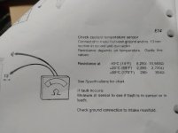
240 93 240/244 ecu coolant sensor fault test
- Thread starter RickATL
- Start date
dl242gt
The world of the smiling Dogo
- Joined
- Jun 21, 2002
- Location
- S NJ, a suburb of Phila.
I forget where it is on the connector. But you can use a good ground on the body like the mounting bracket for the ecu. You will want to test to ground on both the fuel ecu and the icu since they both use the two circuits in the sensor.
Thanks for the help. I tried to delete the post because i found a ground, but i dont see where to delete a thread. Since i couldnt find where to delete, i changed it to what the reading i got means.I forget where it is on the connector. But you can use a good ground on the body like the mounting bracket for the ecu. You will want to test to ground on both the fuel ecu and the icu since they both use the two circuits in the sensor.
ZVOLV
<Master Tech>
- Joined
- Nov 19, 2002
- Location
- California
7.0 on a 20K scale means 7000 ohms.
dl242gt
The world of the smiling Dogo
- Joined
- Jun 21, 2002
- Location
- S NJ, a suburb of Phila.
That seems a bit high in my experience. They usually measure about 4k or so when ambient temps are around the 70s F.
I don't know where it might be online. The Haynes manual and the Bentley both have a temp to resistance chart. It is in the green books online at ozvolvo.org.
I don't know where it might be online. The Haynes manual and the Bentley both have a temp to resistance chart. It is in the green books online at ozvolvo.org.
MasterBlaster
Well-known member
- Joined
- Feb 16, 2009
- Location
- Port Coquitlam
Those 3 numbers in your chart seem to correspond to ball-freezing cold, nice summer morning, and normal operating temperature.
My ancient Mitchell program says:
212 - 180-190
176 - 340-360
140 - 500-600
104 - 1000-1200
68 - 2200-2400
32 - 5800-6000
-4 - 15,000-16,000
7k would seem to be telling the ECU that the temp is in the high 20's(F) (a bit below freezing), and therefore please dump more fuel in to compensate. How's your gas mileage?
As stated earlier, also test on pin 2 of the EZK ignition computer. The sensor has 2 resistors in it, separate from each other, though supposedly identical values, sharing a common ground.
dl242gt
The world of the smiling Dogo
- Joined
- Jun 21, 2002
- Location
- S NJ, a suburb of Phila.
The other thing that can happen is the car never goes into closed loop if the resistance doesn't go to a low enough value. So your mileage is bad and you will see smoking exhaust from the rich mixture.
Make sure to test at three temperatures. Cold, warm, and fully up to temp.
Make sure to test at three temperatures. Cold, warm, and fully up to temp.
The other thing that can happen is the car never goes into closed loop if the resistance doesn't go to a low enough value. So your mileage is bad and you will see smoking exhaust from the rich mixture.
Make sure to test at three temperatures. Cold, warm, and fully up to temp.
Its not running yet. Its throwing the coolant temp sensor fault on both the 2 and 6 diagnostics. Worked on it all day today. It starts, but then shuts off. I started by replacing the crank speed sensor (that was a nightmare) The fault testing seems to indicate a ground problem at the intake manifold. Im doing a complete reconditioning, and i thought that maybe because i powder coated the fuel rail, it was insulating the connection. I sanded the areas around the three bolt that attach the fuel rail to the manifold, but when i checked the ignition control #s 20 and 14, the 20 had a lot of resistance and the 14 read a 1/ infinity.
I read another thread about the ground wire being pressed together where the black comes off the fuel rail and becomes three, and sometimes comes apart. I cut the plastic away and found that area, but it doesnt look bad. The other thread advised to torch the area where they meet so it melts together, but im a little afraid to do it that close to the fuel rail.
bobxyz
Board Member
- Joined
- Aug 29, 2014
- Location
- Boulder CO
With the key off, measure resistance from the ground wire ring terminals (e.g. the crimp on ring terminal) to the battery - post. This should be ~0 ohms if it's making good contact to the manifold, and if the woven ground cable from the valve cover to the bulkhead is good.
You can also unplug the temp. sensor and measure resistance from each sensor pin to battery - post. Both should be the same, and about 2.0K ohms at 70deg.
Don't use a propane torch on the solder joint -- it will likely not work and can easily damage the wires/connection and anything else nearby. If the above measurements are OK, but the measurement at the EZK/ECU connector (with sensor plugged back in) are bad, then re-inspect both the manifold ground wires and the valve cover ground strap.
With the key off, measure resistance from the ground wire ring terminals (e.g. the crimp on ring terminal) to the battery - post. This should be ~0 ohms if it's making good contact to the manifold, and if the woven ground cable from the valve cover to the bulkhead is good.
You can also unplug the temp. sensor and measure resistance from each sensor pin to battery - post. Both should be the same, and about 2.0K ohms at 70deg.
Don't use a propane torch on the solder joint -- it will likely not work and can easily damage the wires/connection and anything else nearby. If the above measurements are OK, but the measurement at the EZK/ECU connector (with sensor plugged back in) are bad, then re-inspect both the manifold ground wires and the valve cover ground strap.
Thanks, ill be trying your list this morning.
So the brown ground off the manifold is infinity (not sure thats the right term.) I measured it at the ring and crimp and both read the same. That would mean my problem is somewhere along those brown and then black and brown wires correct?With the key off, measure resistance from the ground wire ring terminals (e.g. the crimp on ring terminal) to the battery - post. This should be ~0 ohms if it's making good contact to the manifold, and if the woven ground cable from the valve cover to the bulkhead is good.
You can also unplug the temp. sensor and measure resistance from each sensor pin to battery - post. Both should be the same, and about 2.0K ohms at 70deg.
Don't use a propane torch on the solder joint -- it will likely not work and can easily damage the wires/connection and anything else nearby. If the above measurements are OK, but the measurement at the EZK/ECU connector (with sensor plugged back in) are bad, then re-inspect both the manifold ground wires and the valve cover ground strap.
dl242gt
The world of the smiling Dogo
- Joined
- Jun 21, 2002
- Location
- S NJ, a suburb of Phila.
This is with the brown ground connected correct? Infinity there would mean from the manifold connection to the battery is open. If you measure that with continuity ohm metter also check from the computer to the manifold ring terminal.
You should measure approx zero ohms from the manifold terminal to the battery negative as Bob pointed out. Infinity there is an open connection from there to the battery negative. Good to also make sure the ground wire goes to the computer connection with approx zero ohms as well.
You should measure approx zero ohms from the manifold terminal to the battery negative as Bob pointed out. Infinity there is an open connection from there to the battery negative. Good to also make sure the ground wire goes to the computer connection with approx zero ohms as well.