• Hello Guest, welcome to the initial stages of our new platform!
    You can find some additional information about where we are in the process of migrating the board and setting up our new software here

    Thank you for being a part of our community!

122s B18 Judson Positive Displacement Supercharger

Something I would look into while rebuilding is the squish as well. I found on the 2130cc B20 in my 140, with a ported head it would ping at around 11* base timing with a stock Elring HG. Just swapping to a thinner .036" Cometic instead of the .049" compressed Elring, the pinging went away completely. Even at 17* base timing it was fine. Now on MS it can handle a good bit of timing without any pinging on 89* or 91*.

For the ignition, as Ken mentioned, 75 was the only year for a factory electronic on the B20 and tweaking the timing curve on the associated box hasn't been cracked yet. You can run just the dizzy and a MSD or the like though, did that for years on mine. Otherwise look into the 123 distributors. Programmable, drop-in ready, seem to have a decent rep from what I've seen so far, and relatively stock looking as well.
 
its not about compression ratio, the reason for trying to steer away from the hybrid b18/b20 is the poorly managed burn characteristics that are directly correlated to oversized combustion chamber shape compared to bore. The burn management creates hot spots that lead to detonation (and no matter how much you finesse timing those hotspots are still there acting like glow plugs). After my experience with a boosted hybrid motor, and then building a proper b20 bottom end to go along with it. I would never do it again, or recommend that anyone do it. My new motor pulled harder at ~7psi than the hybrid did at 18psi.

gsellstr said:
Something I would look into while rebuilding is the squish as well. I found on the 2130cc B20 in my 140, with a ported head it would ping at around 11* base timing with a stock Elring HG. Just swapping to a thinner .036" Cometic instead of the .049" compressed Elring, the pinging went away completely. Even at 17* base timing it was fine. Now on MS it can handle a good bit of timing without any pinging on 89* or 91*.

For the ignition, as Ken mentioned, 75 was the only year for a factory electronic on the B20 and tweaking the timing curve on the associated box hasn't been cracked yet. You can run just the dizzy and a MSD or the like though, did that for years on mine. Otherwise look into the 123 distributors. Programmable, drop-in ready, seem to have a decent rep from what I've seen so far, and relatively stock looking as well.


Since a carbureted B20 head worked exceptionally well w/a B18 bore with my other blower, let me ask you and others this: What is the difference in the shape of the combustion chamber and the CR between it and that of a F head??
 
Last edited:
Since a carbureted B20 head worked exceptionally well w/a B18 bore with my other blower, let me ask you and others this: What is the difference in the shape of the combustion chamber and the CR between it and that of a F head??

Pretty sure that all b18/b20's use the same bathtub chamber shape, with a squish pad on the passenger side. The only differences are going to be how wide the combustion chamber is. I cant directly comment as to the difference between say an A head and and F head, but I can say that my NA form b18/b20 hybrid compared to my NA b18 was a dog until wound to 6-7k

You say it worked "exceptionally well" but have you driven a properly built b20 running boost? Have you compared a b18/b20 hybrid to a b20 with the same boost, timing, fuel consumption?
 
The issue would be if the combustion chamber is wider than the bore. That's just one more protruding edge in there.

On my PV's engine, I found an R-Sport head on eBay. Lots or really good aspects to it (huge valves, great worked ports, double valve springs, etc), but it had been shaved down to a ridiculous degree. To something like a 12:1 CR on a 2.0L bottom end, and I was putting it on top of a 2.1L (92.5mm bore) bottom end, so it would be even higher. But raising the head away from the piston to decrease CR would just make it more detonation prone, until the CR was finally low enough to counteract that. And low CR motors just aren't as peppy. My solution was to use some dished B21 pistons to lower the CR, and build it with a .036 squish. Net result is 155 - 160 HP at the wheels (calced from 1/4 mile speeds) and it runs just fine on pump 93 octane. Ping resistant enough that you can advance the power of the front end of the timing curve - no pinging but it starts making less power.
 
Pretty sure that all b18/b20's use the same bathtub chamber shape, with a squish pad on the passenger side. The only differences are going to be how wide the combustion chamber is. I cant directly comment as to the difference between say an A head and and F head, but I can say that my NA form b18/b20 hybrid compared to my NA b18 was a dog until wound to 6-7k

You say it worked "exceptionally well" but have you driven a properly built b20 running boost? Have you compared a b18/b20 hybrid to a b20 with the same boost, timing, fuel consumption?

No, I aways ran B18 or B18's I bored out to a B20 specs w/a B18 head and a thick head gasket.

The sedan I had the blower on was a .020 over B18 w/a carbureted B20 head, a new stock cam and it pulled strongly all the way from about 1500 rpm to 5000.

Here in Vermont there are hills and mountains everywhere and the supercharged engine would pull most all of them in 4th gear and accelerate if you wanted to. With a stock B18 or B20 3rd gear would be necessary.

This was also using much better gas (late-70s) compared to what is used today. Maybe what worked then does not work today because of the added ethanol?
 
Last edited:
from my recent experiences, a b20 bored .030 with a piston to head clearance of .030 (rather tight squish), and a k-cam, and E head (9.5:1 static CR) running ~7# of boost out of a TD04HL-15g turbo, pulls harder on the same fuel and timing map than the B18, bored .040, piston to head at ~.050, and the same head, running 18# from the same turbo. the static CR was about 7.7 on the b18/b20 hybrid

Personally, I would rather have a thin head gasket and carve the crap out of the combustion chambers than a thick head gasket to lower the static CR.
 
Last edited:
<a data-flickr-embed="true" href="https://www.flickr.com/photos/68431219@N02/27155314671/in/photostream/" title="B18"><img src="https://c8.staticflickr.com/8/7480/27155314671_b18520800f_z.jpg" width="640" height="542" alt="B18"></a><script async src="//embedr.flickr.com/assets/client-code.js" charset="utf-8"></script>

Here is a photo above of the B18 head that came off of this engine w/the larger part of the squish area on the left-hand side of the engine.

Based on what some of you have learned and experienced it seems like a good time to take look at the various combustion chambers.

I found a photo of a E head combustion chamber below. Is the F head chamber the same basic shape even though its CR is lower?

Have not seen a carbureted B20 head in a long time and I am wondering if it is patterned after the B18 head or is more like the E and F units?

<a data-flickr-embed="true" href="https://www.flickr.com/photos/68431219@N02/27131985002/in/dateposted/" title="E chamber"><img src="https://c3.staticflickr.com/8/7673/27131985002_99a0dbaefc_z.jpg" width="640" height="568" alt="E chamber"></a><script async src="//embedr.flickr.com/assets/client-code.js" charset="utf-8"></script>
 
Yeah, the shape is nearly identical, the depth is where the cr differs. But the difference between the b18 and b20, look at how far the chamber is from the fire ring.
 
<a data-flickr-embed="true" href="https://www.flickr.com/photos/68431219@N02/26659819453/in/dateposted/" title="Screen Shot 2016-05-25 at 1.46.17 PM"><img src="https://c6.staticflickr.com/8/7589/26659819453_7a9899ecbf_z.jpg" width="640" height="368" alt="Screen Shot 2016-05-25 at 1.46.17 PM"></a><script async src="//embedr.flickr.com/assets/client-code.js" charset="utf-8"></script>

Have started researching the effects of supercharger boost on an engine and at what point detonation occurs without using a boost ignition retard device.

The chart shows the effective compression ratio of an engine, which combines the static compression ratio with the amount of supercharger boost. For most street applications with 93 octane pump gas the effective compression ratio needs to be kept below about 12.0:1

In my case if I go this route I need to shoot for 8.5:1 or lower as at six-seven psi of boost the Judson Supercharger puts out the effective compression ratio is 12.0:1 - 12.5:1

Even a B18B head with a CR Of 8.7:1 it will need to be lowered by making the combustion chamber larger.

Maybe if go this way, at the same time I will install larger valves and hard valve seats and port the head a bit.

Does anyone here know what size of larger valves will work well for a B18 head and where do the ports need to be changed keeping in mind this will be street driven?

Has anyone here put a supercharger or a turbo on a B18 w/a B/18 head? What were your experiences?
 
B18's use 11/32" valves and a single groove keeper. Conversion guides are available to allow the use of 5/16" B20 valves with 2 groove keepers. Oversize stainless steel valves are readily available as are hardened keepers.

If you can find one, early B18A/B18D heads are 8.5:1.
 
B18's use 11/32" valves and a single groove keeper. Conversion guides are available to allow the use of 5/16" B20 valves with 2 groove keepers. Oversize stainless steel valves are readily available as are hardened keepers.

If you can find one, early B18A/B18D heads are 8.5:1.

Thanks!!
 
<a data-flickr-embed="true" href="https://www.flickr.com/photos/68431219@N02/27287596711/in/dateposted/" title="Judson Supercharger 1"><img src="https://c8.staticflickr.com/8/7396/27287596711_e21a0f9de0_b.jpg" width="1000" height="716" alt="Judson Supercharger 1"></a><script async src="//embedr.flickr.com/assets/client-code.js" charset="utf-8"></script>

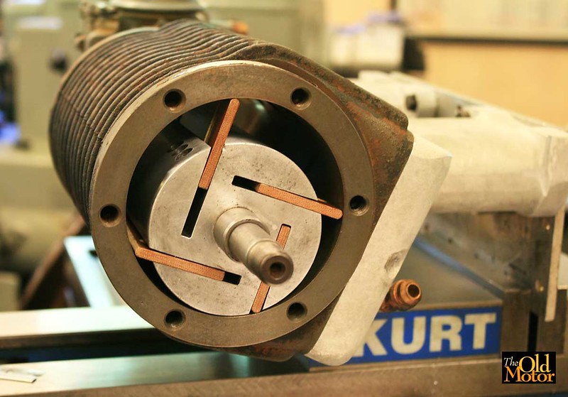
I have been to busy with customers cars lately, but managed to clean up all of the Judson Supercharger parts and give it a good inspection. I bought it all apart but it is 99% complete and is only missing a few common fasteners. It only needs a routine rebuild with new bearings, seals, and gaskets, but I will need to machine a new set of fiber vanes for it which is not that big of a deal.

This set of photos gives you a very good idea of how it is constructed and what all of the parts look like. To get a better idea of how it all works take a look at the first post in this thread which explains it.

This pales in comparison to the modern turbos and controls many of you are installing, but is going on a 1968 122s Wagon (the shop truck) that is being modified with only bolt on high performance vintage pieces from the 1960s and early-1970s. When installed (takes 3-4 hrs) on a stock engine with no other changes it is capable of a 30% HP increase and the engine should put out about 150 HP with the added 6-7 psi boost.

<a data-flickr-embed="true" href="https://www.flickr.com/photos/68431219@N02/27358159615/in/photostream/" title="Judson Supercharger 2"><img src="https://c8.staticflickr.com/8/7476/27358159615_c174c4aa6f_b.jpg" width="1000" height="671" alt="Judson Supercharger 2"></a><script async src="//embedr.flickr.com/assets/client-code.js" charset="utf-8"></script>

<a data-flickr-embed="true" href="https://www.flickr.com/photos/68431219@N02/26751751843/in/photostream/" title="Judson Supercharger 3"><img src="https://c4.staticflickr.com/8/7059/26751751843_bd0e457c5b_b.jpg" width="1000" height="872" alt="Judson Supercharger 3"></a><script async src="//embedr.flickr.com/assets/client-code.js" charset="utf-8"></script>

The carburetor is a simple one-barrel Holley unit that was used on 220 ci six cylinder cars and trucks in the 1950s and early sixties that is more than big enough for the 108.5 ci B18. It is not very sophisticated (in fact with the glass float bowl it looks like a toilet mechanism), but will serve well after a rebuild to get the system set up and running and have a base line to compare to future changes.

<a data-flickr-embed="true" href="https://www.flickr.com/photos/68431219@N02/26750702114/in/photostream/" title="Judson Supercharger 4"><img src="https://c3.staticflickr.com/8/7445/26750702114_d5727e3a9d_b.jpg" width="1000" height="770" alt="Judson Supercharger 4"></a><script async src="//embedr.flickr.com/assets/client-code.js" charset="utf-8"></script>

<a data-flickr-embed="true" href="https://www.flickr.com/photos/68431219@N02/27358183645/in/photostream/" title="Judson Supercharger 5"><img src="https://c6.staticflickr.com/8/7059/27358183645_4c86672104_b.jpg" width="1000" height="702" alt="Judson Supercharger 5"></a><script async src="//embedr.flickr.com/assets/client-code.js" charset="utf-8"></script>

<a data-flickr-embed="true" href="https://www.flickr.com/photos/68431219@N02/26384206164/in/dateposted/" title="jud"><img src="https://c5.staticflickr.com/8/7054/26384206164_2aabc5c301_b.jpg" width="809" height="221" alt="jud"></a><script async src="//embedr.flickr.com/assets/client-code.js" charset="utf-8"></script>

<a data-flickr-embed="true" href="https://www.flickr.com/photos/68431219@N02/27287658791/in/dateposted/" title="Judson Supercharger 6"><img src="https://c8.staticflickr.com/8/7561/27287658791_a50526ac07_b.jpg" width="1000" height="830" alt="Judson Supercharger 6"></a><script async src="//embedr.flickr.com/assets/client-code.js" charset="utf-8"></script>

<a data-flickr-embed="true" href="https://www.flickr.com/photos/68431219@N02/27324812456/in/photostream/" title="Judson Supercharger 7"><img src="https://c1.staticflickr.com/8/7195/27324812456_c266c1d18b_b.jpg" width="1000" height="738" alt="Judson Supercharger 7"></a><script async src="//embedr.flickr.com/assets/client-code.js" charset="utf-8"></script>

<a data-flickr-embed="true" href="https://www.flickr.com/photos/68431219@N02/27358202135/in/photostream/" title="Judson Supercharger 9"><img src="https://c8.staticflickr.com/8/7512/27358202135_01f13d7a34_b.jpg" width="1000" height="827" alt="Judson Supercharger 9"></a><script async src="//embedr.flickr.com/assets/client-code.js" charset="utf-8"></script>

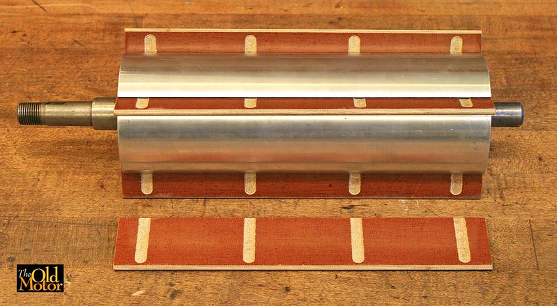
The drive end of the aluminum rotor and shaft. The rotors were precision balanced at 10K RPM.

<a data-flickr-embed="true" href="https://www.flickr.com/photos/68431219@N02/27260500492/in/photostream/" title="Judson Supercharger 10"><img src="https://c5.staticflickr.com/8/7303/27260500492_0f0c982118_b.jpg" width="1000" height="679" alt="Judson Supercharger 10"></a><script async src="//embedr.flickr.com/assets/client-code.js" charset="utf-8"></script>

The crank and blower pulleys.

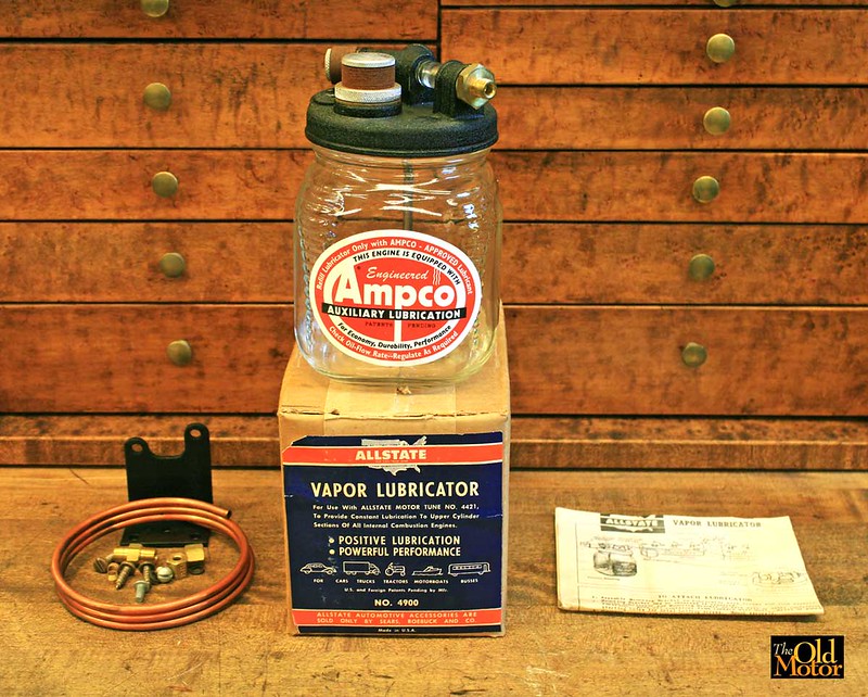
Below is all of the original throttle linkage, the belt, the blower lubricator, and even the air cleaner.

<a data-flickr-embed="true" href="https://www.flickr.com/photos/68431219@N02/27260532772/in/photostream/" title="Judson Supercharger 12"><img src="https://c5.staticflickr.com/8/7356/27260532772_c7b5a747c8_b.jpg" width="1000" height="692" alt="Judson Supercharger 12"></a><script async src="//embedr.flickr.com/assets/client-code.js" charset="utf-8"></script>
 
Last edited:


Summer has been super busy here in the shop getting client's vintage racing cars ready to run at events at both Indy and Milwaukee, rebuilding a 1914 Simplex 4-cyl. 600 ci engine and trying to get a little time in here and there on the Volvo.

The new micarta vanes for the supercharger are finally finished, and you can see them above in the aluminum rotor, mocked up in about the same location in the housing bore that it rotates in (there is clearance below it).

The assembly rotates clockwise, and the right-hand vane is shown about five degrees before it starts to pull in the fuel and air charge from the portion of the aluminum manifold fed by the carburetor at atmospheric pressure. It then compresses it under the rotor; next as it rotates the vane slides out of the rotor slot via centrifugal force, lets the compressed mixture expand until it is forced out of the housing into the intake manifold at a maximum of 5-7 psi.


The intake mixture enters in the bottom half of the blower housing seen above through the diamond shaped openings. The compressed mixture exits through the top half into the intake manifold. The divider helps to equalize the flow to both the front and rear intake runners.


The new vanes above placed in the rotor. They are made of micarda, a tough thermosetting plastic and cloth composite that is the same material used for Volvo "fiber" camshaft gears. The slots assist in collecting the gas, air, and oil mixture to help lubricate the rotor slots and the sides of the vanes.


The housing bore and the rotating assembly will be lubricated by an Ampco "Vapor Lubricator"; this one is a brand new old stock unit. It injects a very fine mist of "Marvel Mystery Oil" or 10 weight oil through a spray nozzle into the carburetor venturi in the amount of about one drop very 4-6 seconds. After passing through the blower, it serves as a top end lube for the intake valve guides, intake valve and seat faces and the cylinder bores and rings.

New pressure-sensitive aluminum ID plate below for the front end of the supercharger housing.

Next up is to hone the ID of the blower housing on the shop Sunnen precision honing machine, in the same manner as a cylinder bore is done. Then detail everything, get new bearings and seals and reassemble it.

 
Last edited:

Good to hear you like this retro system that is an alternative to turbos on pushrod red block B18's - Slowly making progress w/it. Will update when there is more to share.

I am looking for another one for another car if anyone knows where I can find one, PM me - Thanks
 
Last edited:
Back
Top