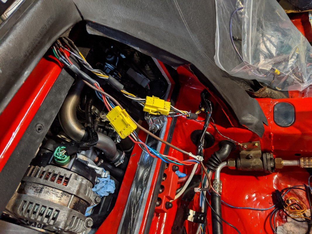
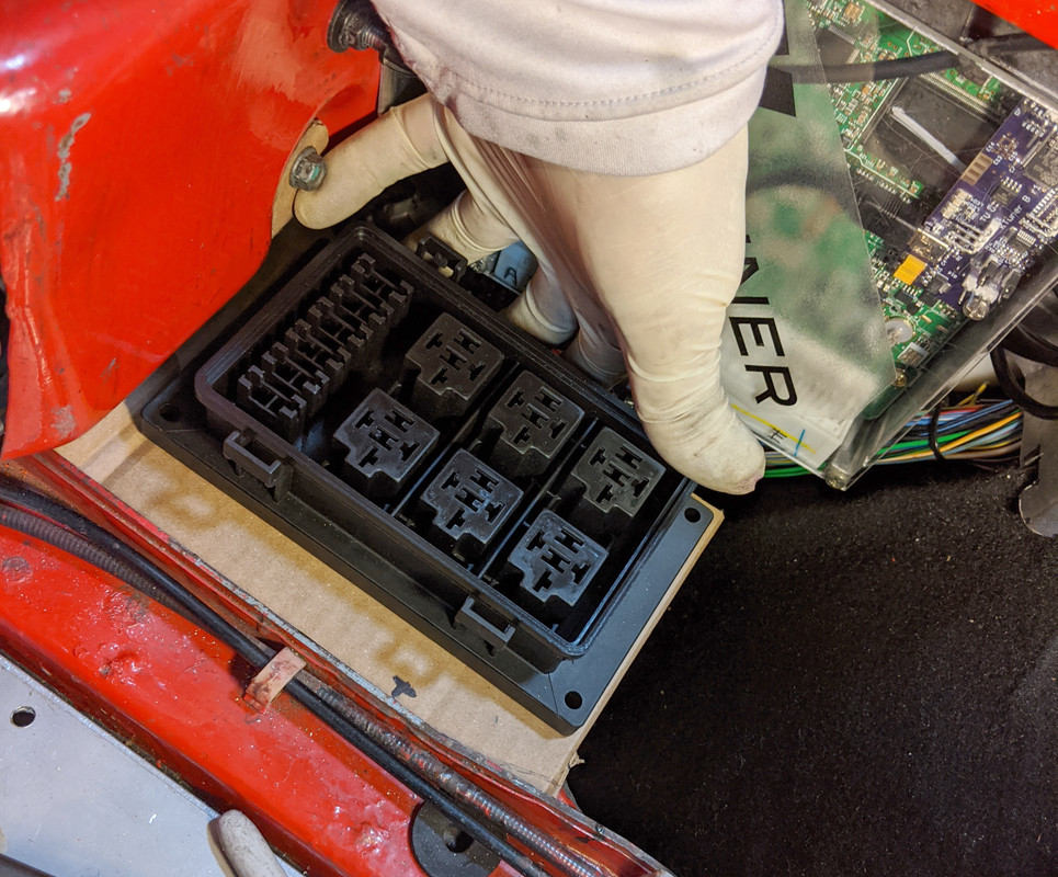
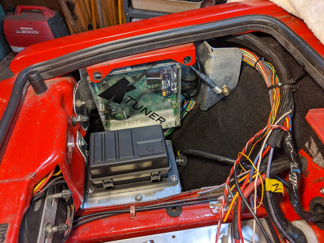
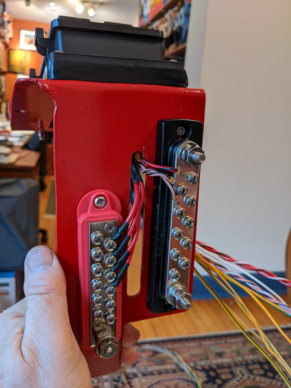
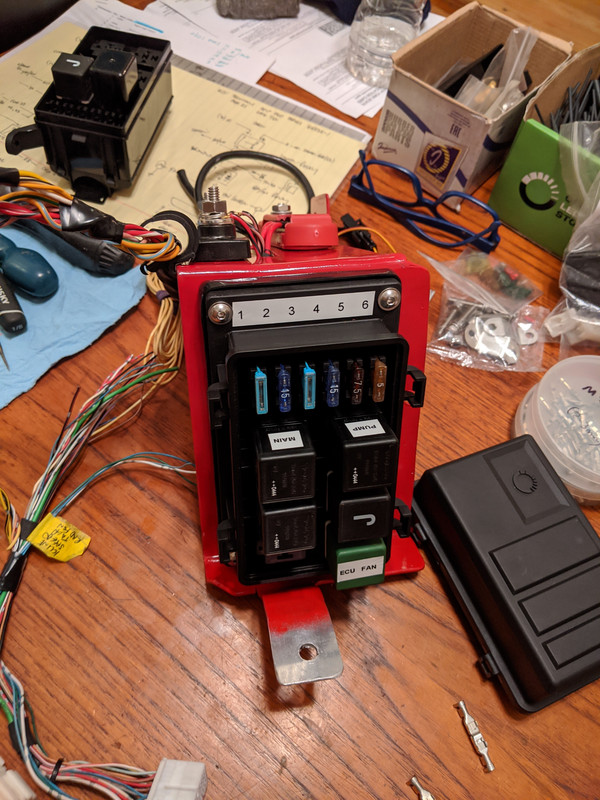
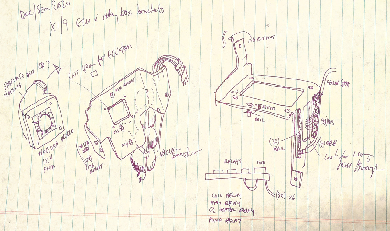
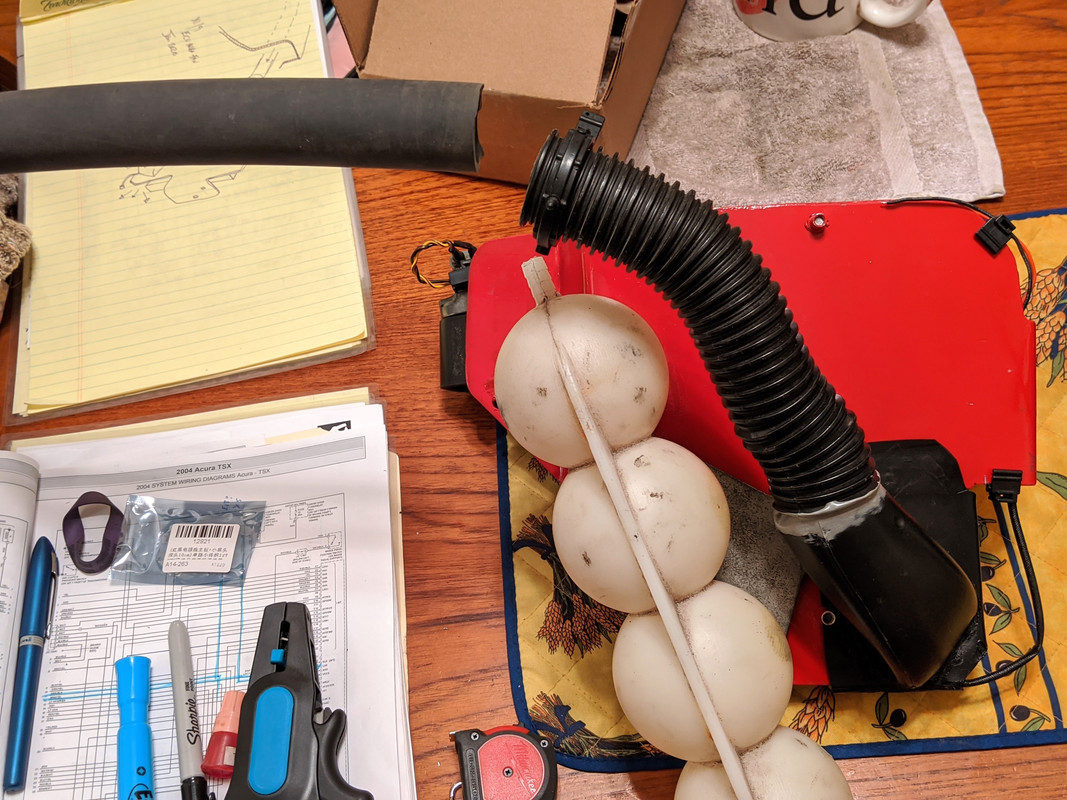
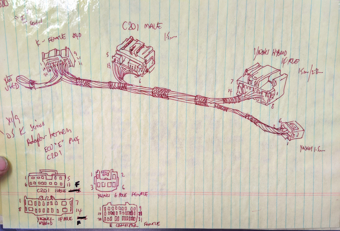
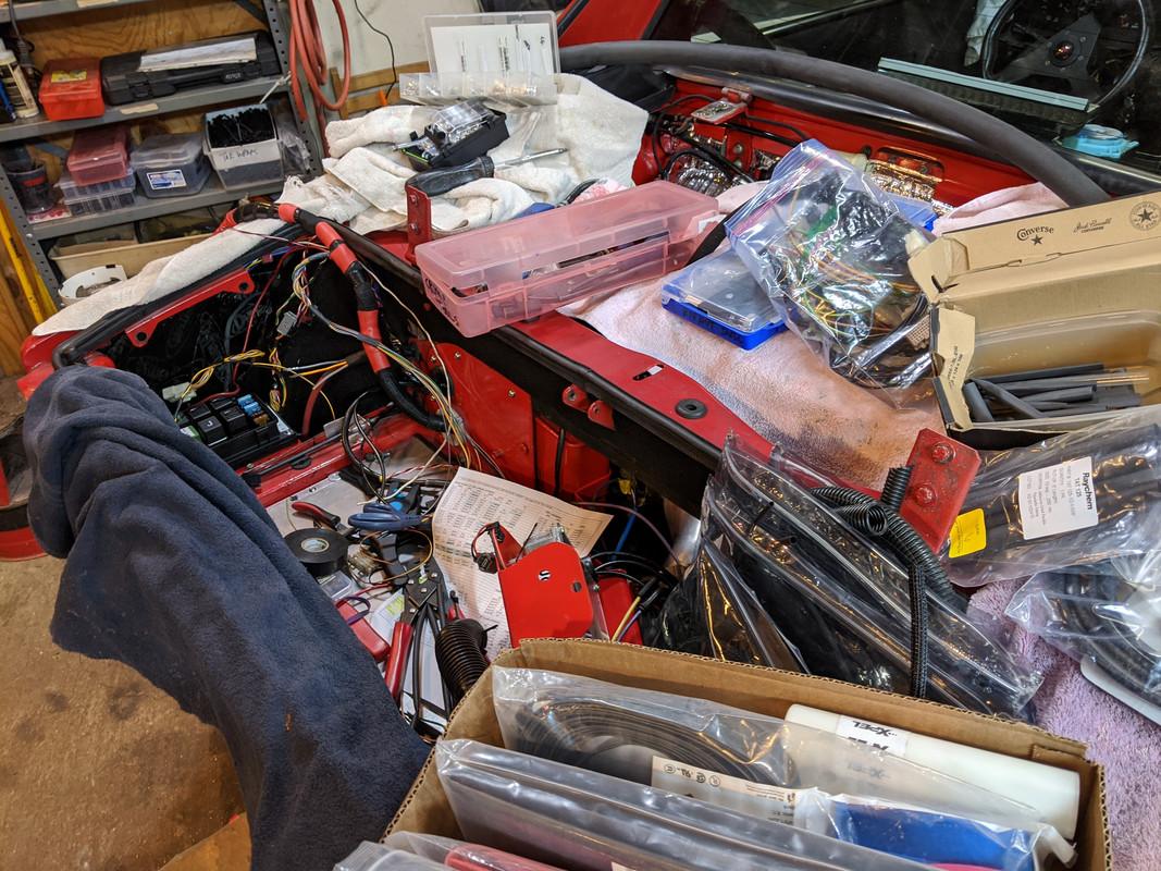
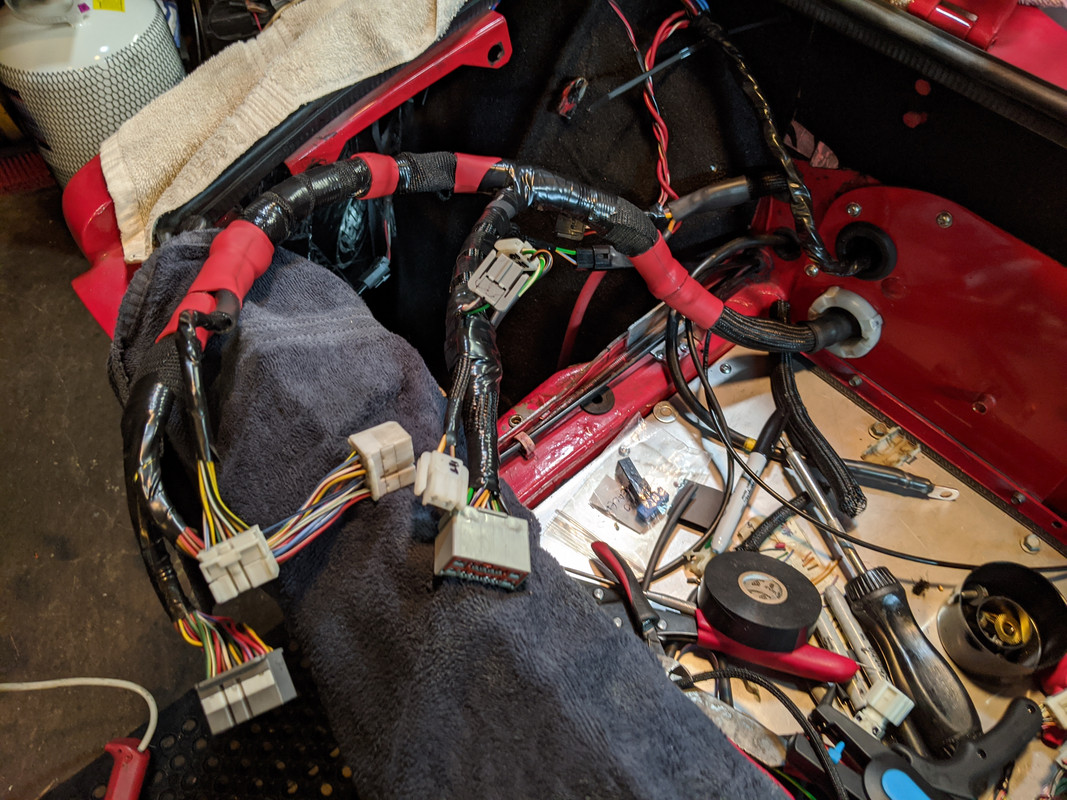
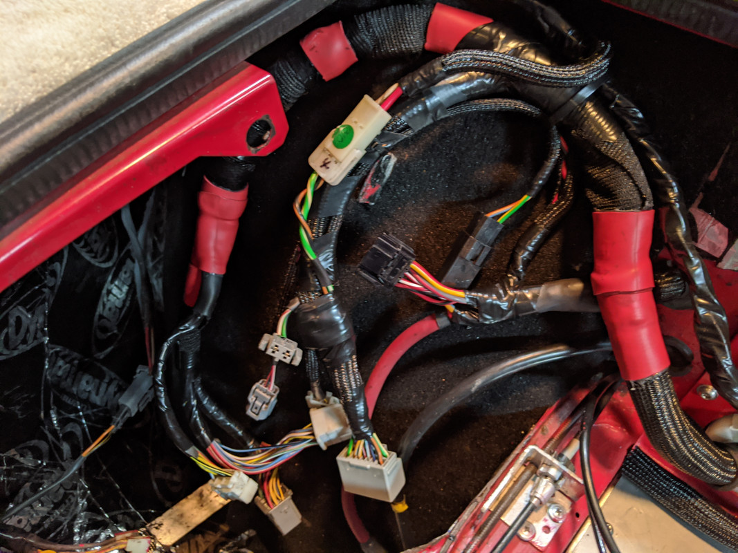
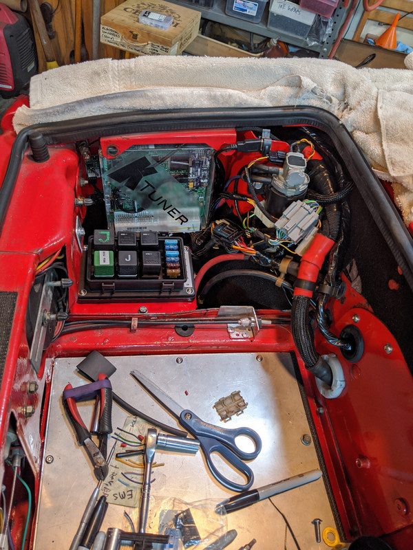
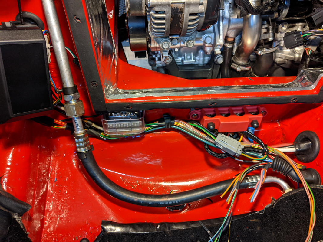
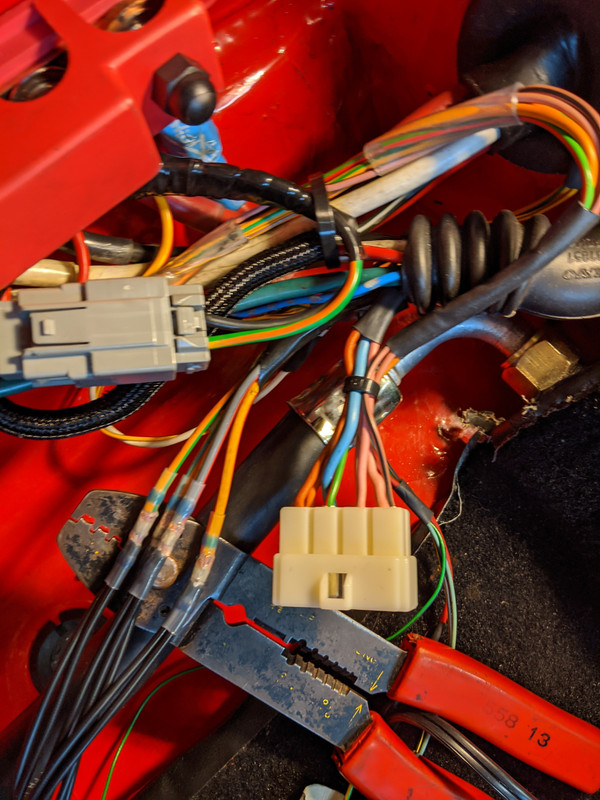
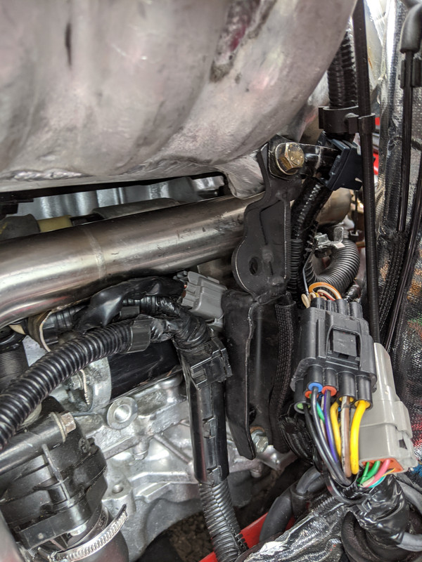
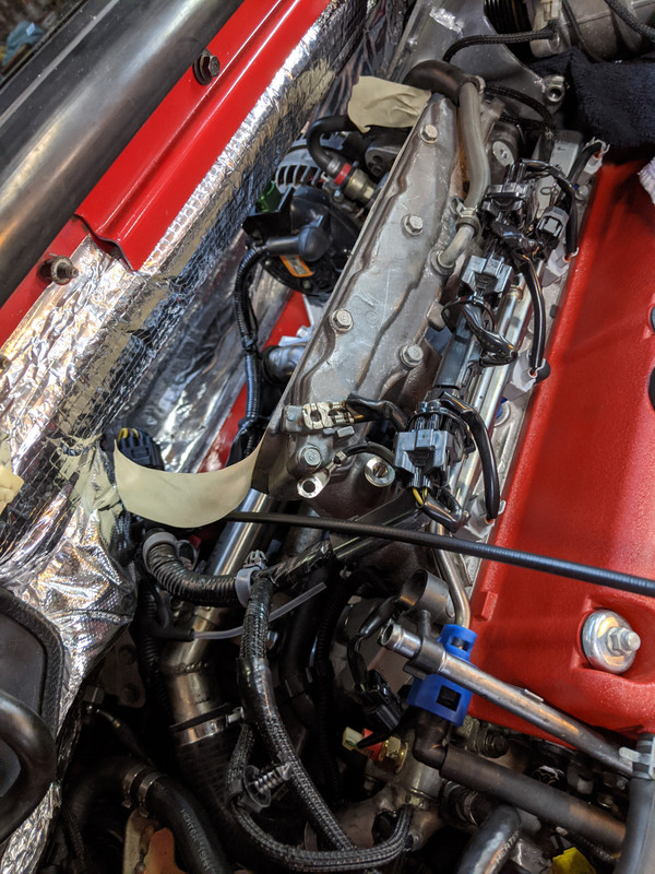
Still plugging away at the electrical wiring - laying out the EMS harness now that I have the various connections figured out. I made an bridge harness (using the pigtail that came with the motor) between the ECU E, C201, relay box and EMS, so that everything can be unplugged if/when the drivetrain requires removal.
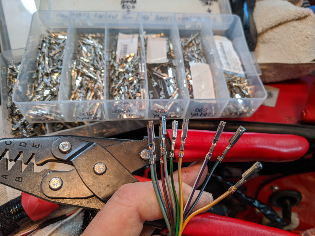
Now it's mostly just a question of connecting all the dots. AMP JPT connectors for much of this, simply because I have them from old Volvo harnesses & they can carry reasonable load. Using Yazaki 1.5 & 2.8 for sensors, signal wires, etc. that don't have the same load requirements.
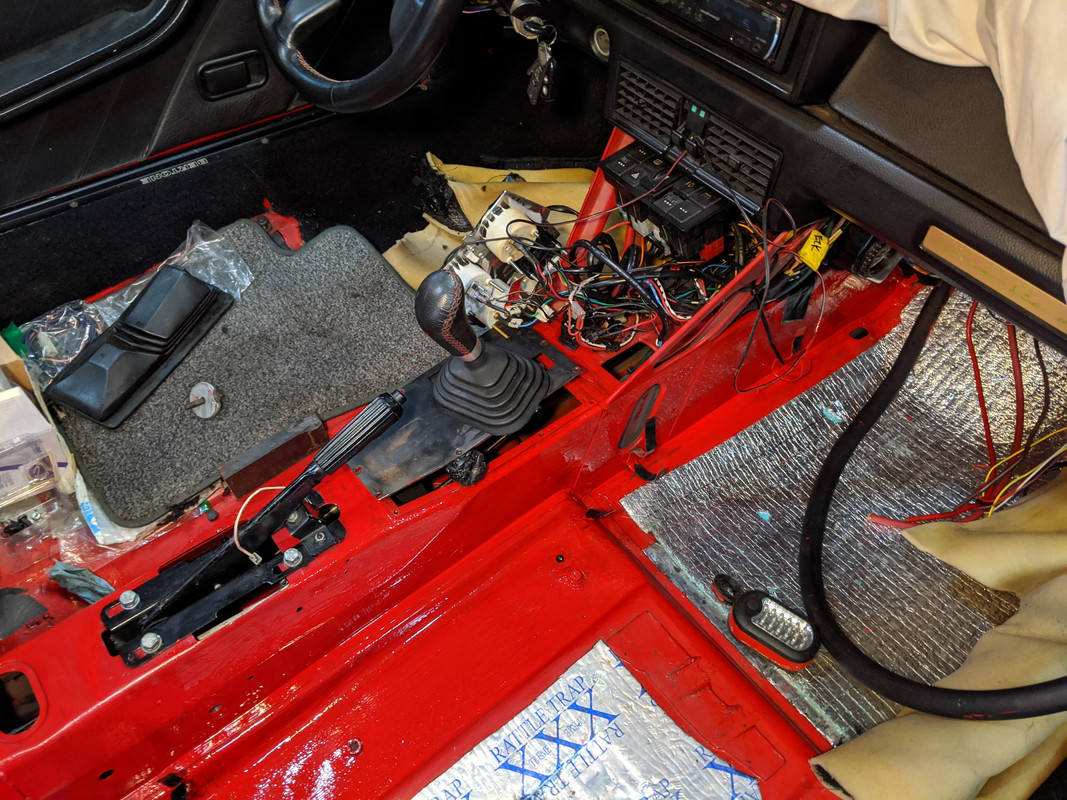
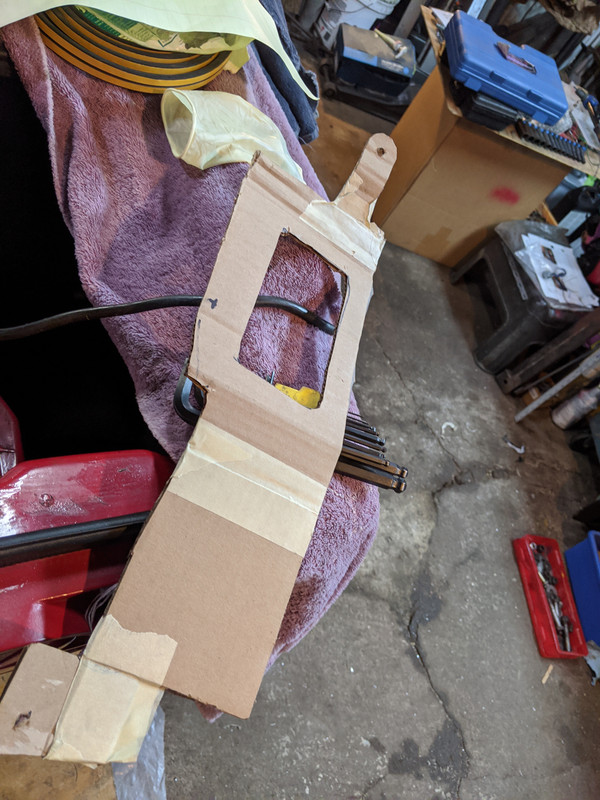
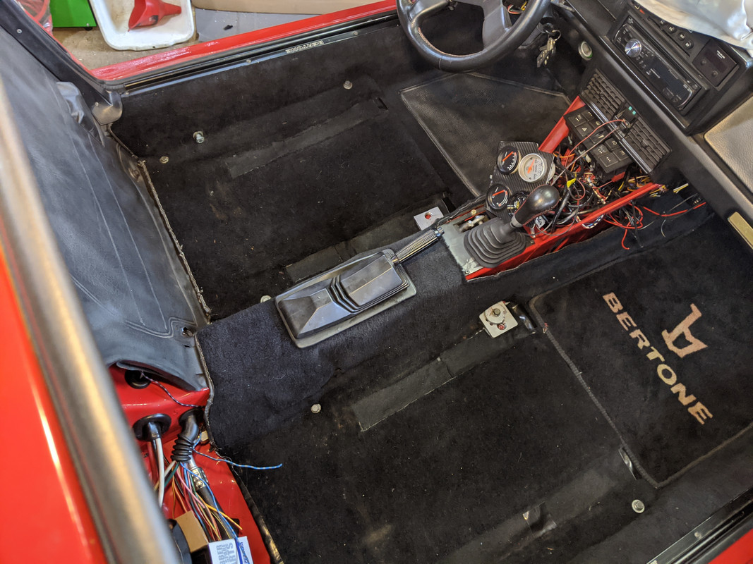
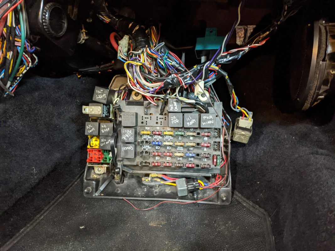
Also putting a couple layers latex on the backside of the remaining Bertone floor mat to help hold it together & create a rubberized layer. Adheres nicely into the mesh grid on the back. Now I wish I had kept the DS mat - I might have been able to save it with this method. Just need it to last another year or so until I'm ready to install the new carpeting & mats.
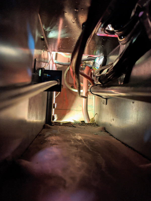
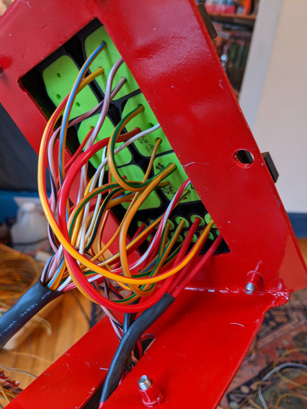
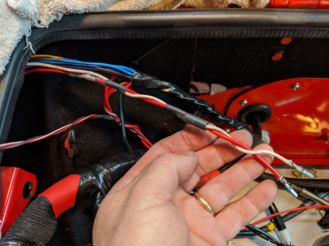
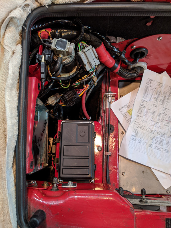
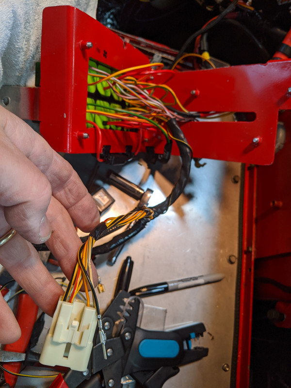
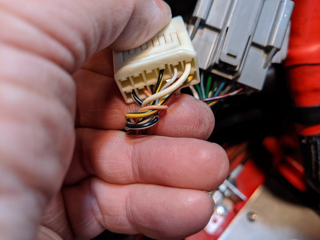
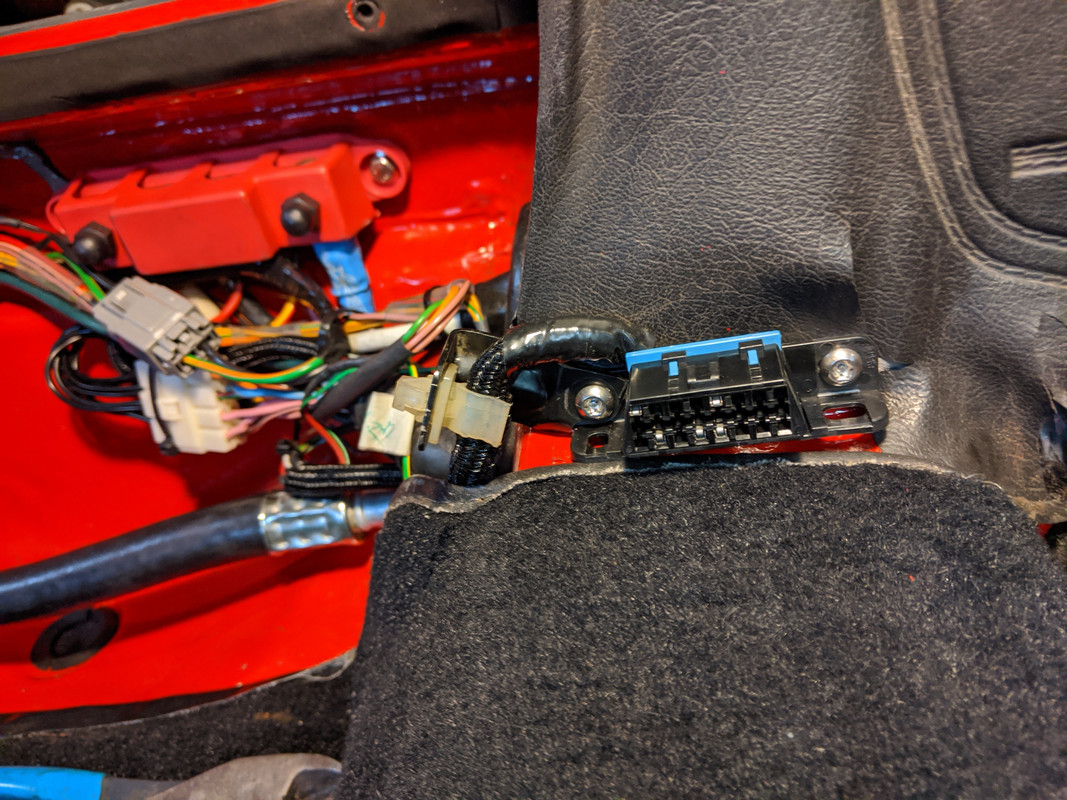
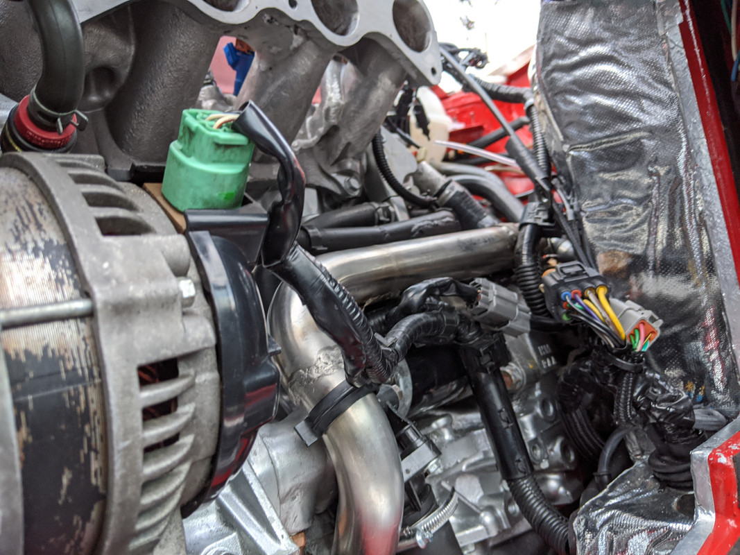
Got some more of the EMS harness connected - these are all the signal/trigger wires that pass from theater-engine EMS harness through to the cabin via two connectors at that end. I bought these crimpers from Cycle Terminal back when I was doing the C30 AWD swap - to take care of the wiring needs for that.
There are issues - I found that I had incorrectly connected a wire on the cabin side of this harness - the one I need for the bay fan thermoswitch I mistakenly connected to the wire intended for the ACfan trigger - which runs all the way to the fusebox instead of terminating in the spare well. I'll have to switch some wires around in the cabin-side connector to address that. Thankfully it's just the that pair.
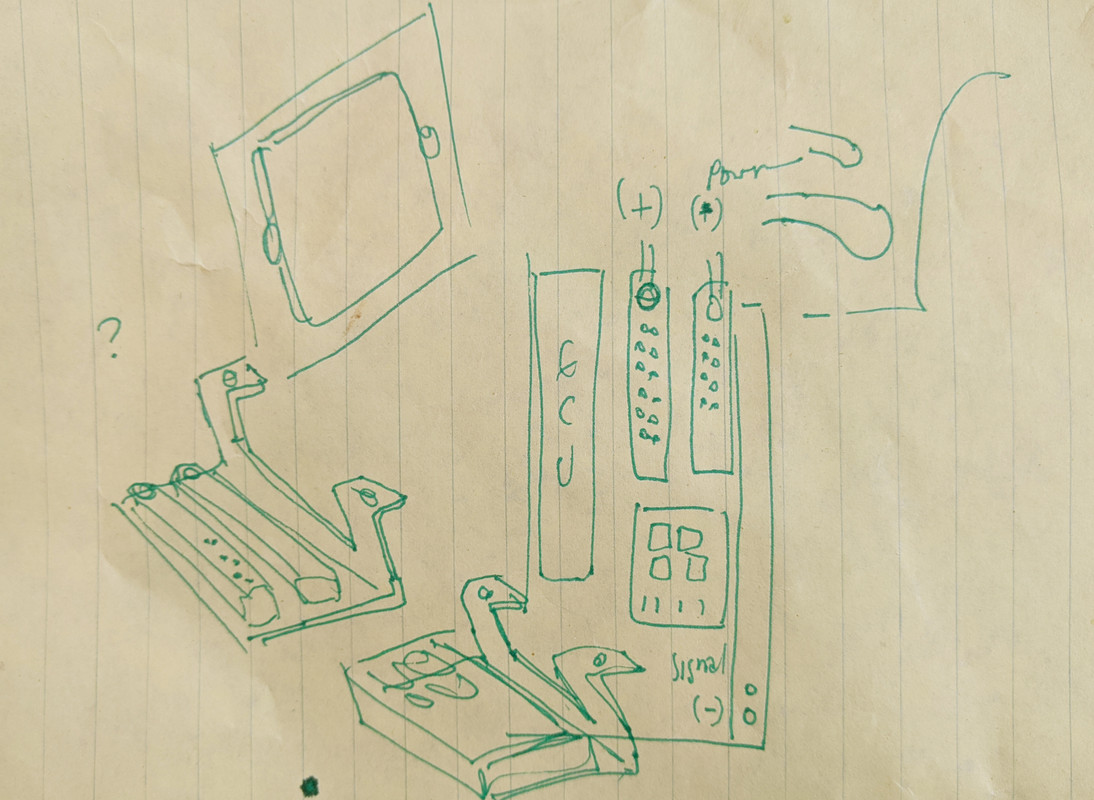
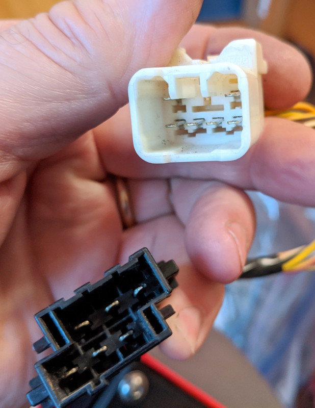
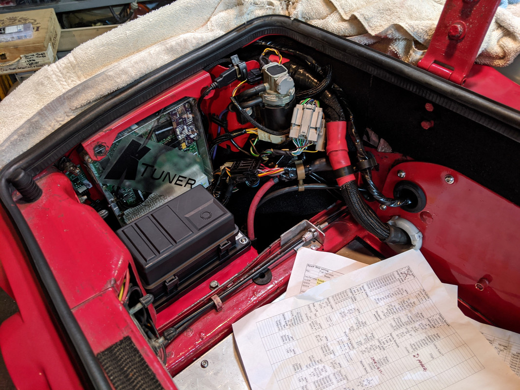
This stuff takes me forever. I've been spending days on making the wiring charts listing the different connectors and all the wiring on each side of every connector. I have to do it multiple ways so I can cross-check each wire as I actually connect it to the appropriate housing. Very time consuming for me. I tend to get dyslexic with this stuff & switch pin numbers/locations in my head or look at the housings from the wrong side when counting pin numbers. The convention seems to be pins are numbered starting top row left, viewed from the wire side of the housing. Some of the sketches I made, I had labelled them viewed from the terminal side or from the male housing, which throws everything off. Fortunately I figured most of that out on paper rather than after doing the wiring itself.
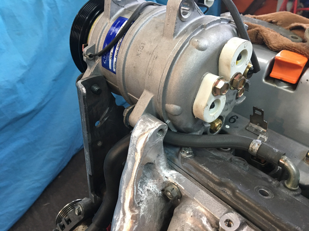
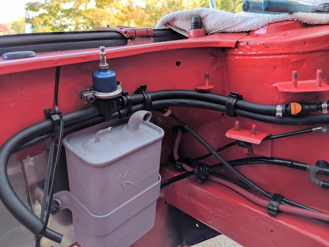
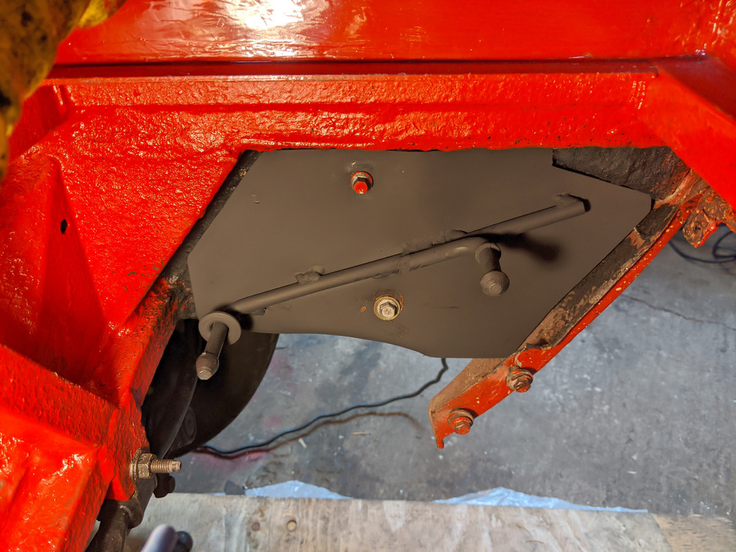
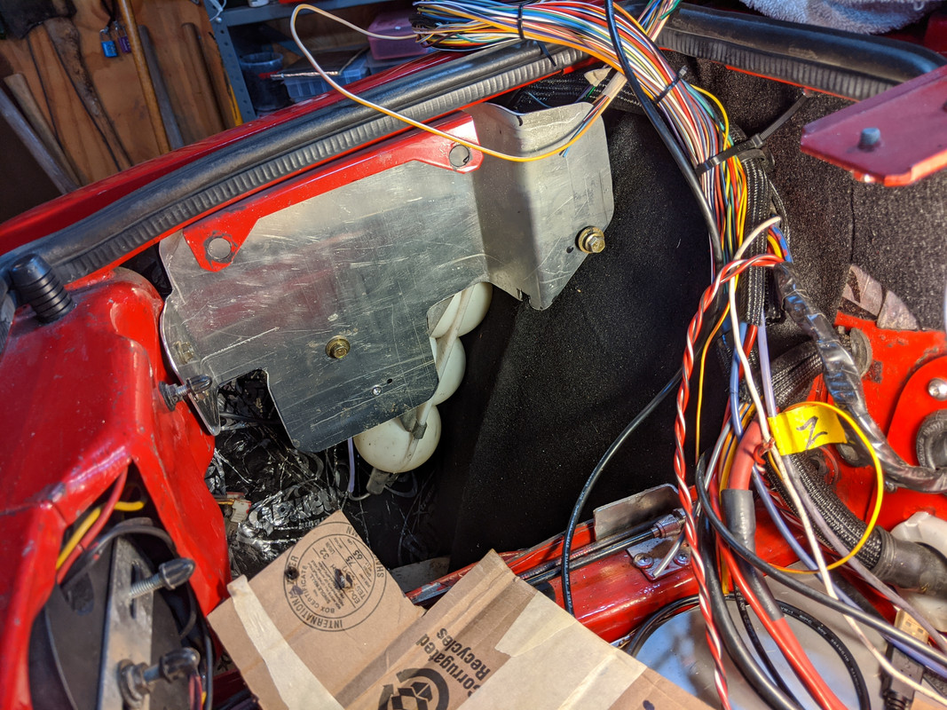
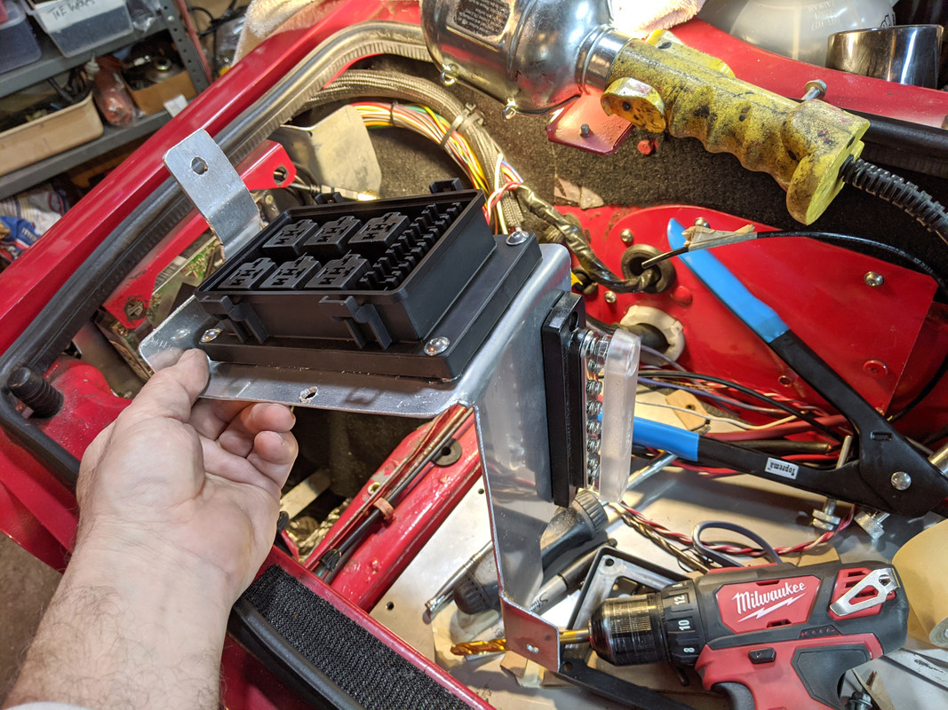
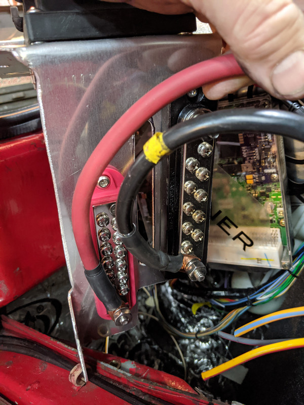
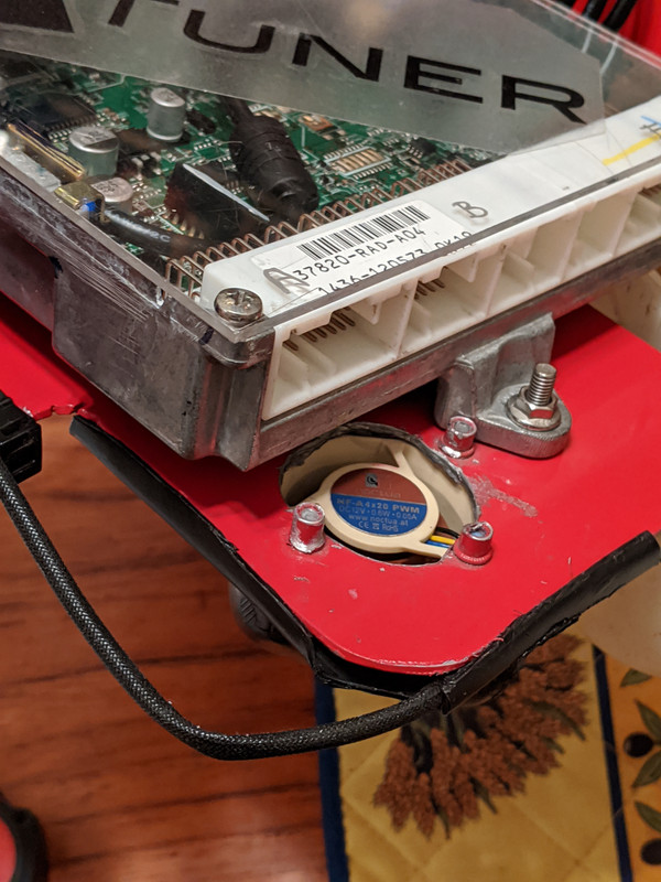
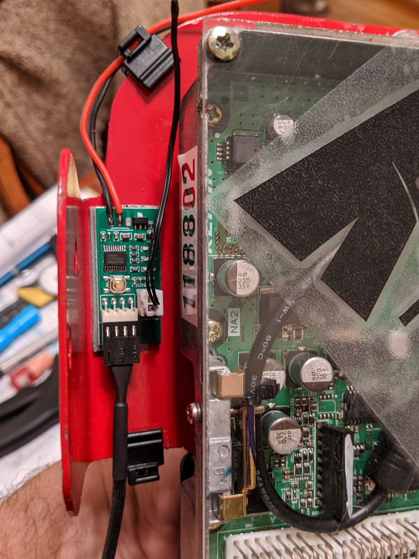
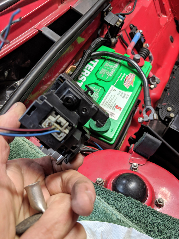
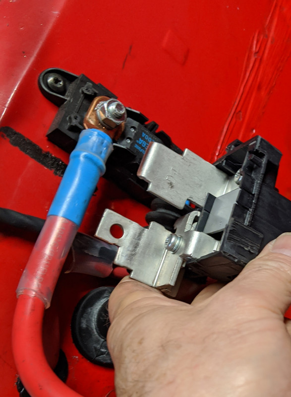
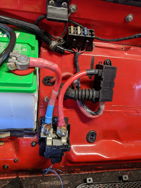
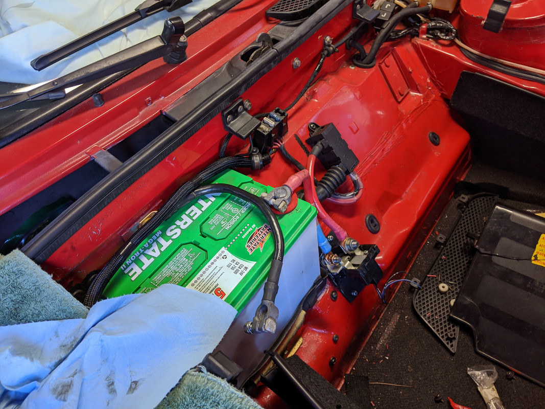
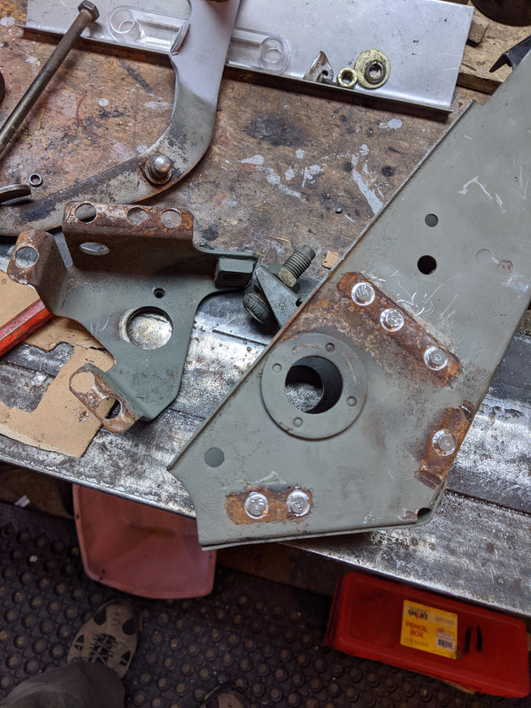
I've also been mulling over whether or not to include the ELD (Electronic Load Detection) circuit Honda builds into the EMS. The ECU controls Alt output based on a load signal from that. If I didn't include it, I would still have to figure out a way to 'fool' it otherwise. I chopped up the Acura fusebox & removed the section that houses the input battery/starter/alt cable attachment, with the ELD module. I considered mounting it in the spare well, which would have been easier, however the unit needs to monitor load before any consumers, or it won't operate correctly, based on what I've read about it.
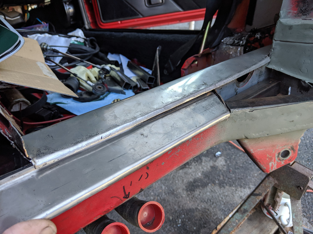
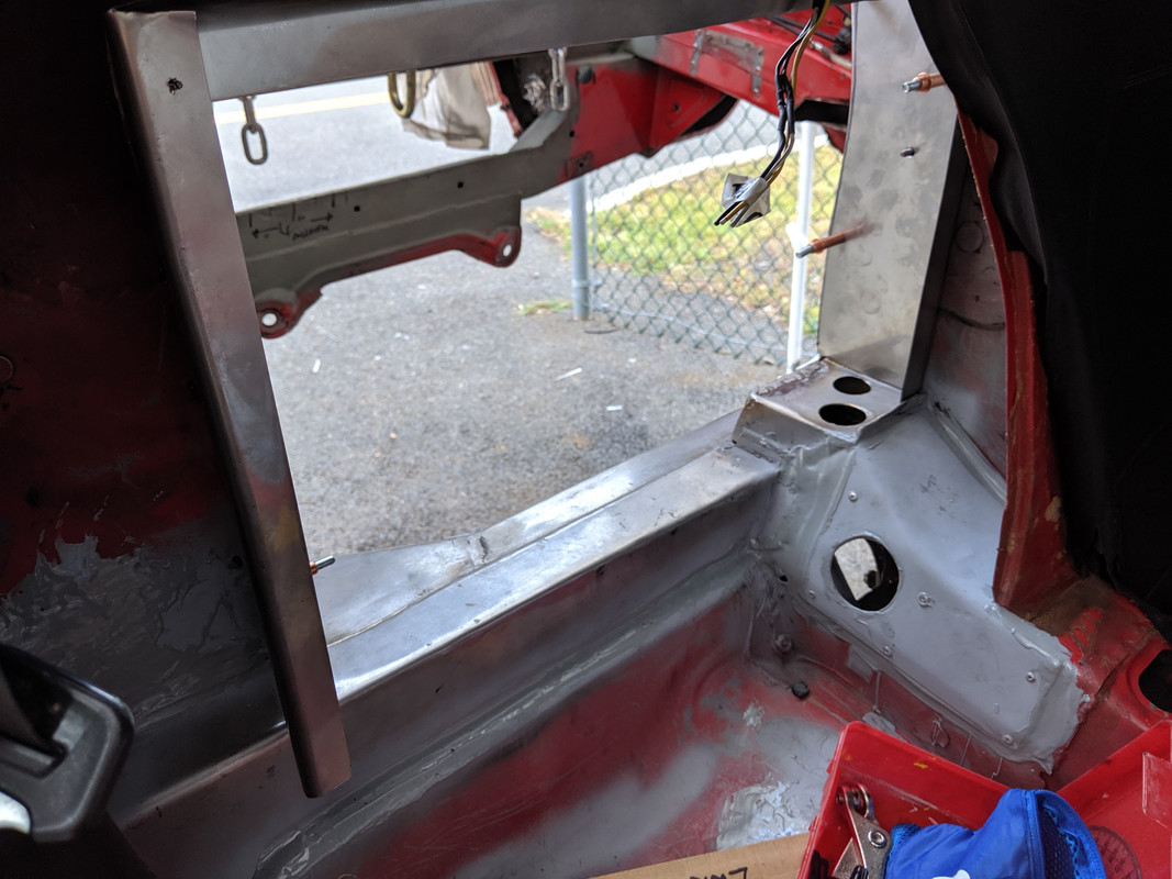
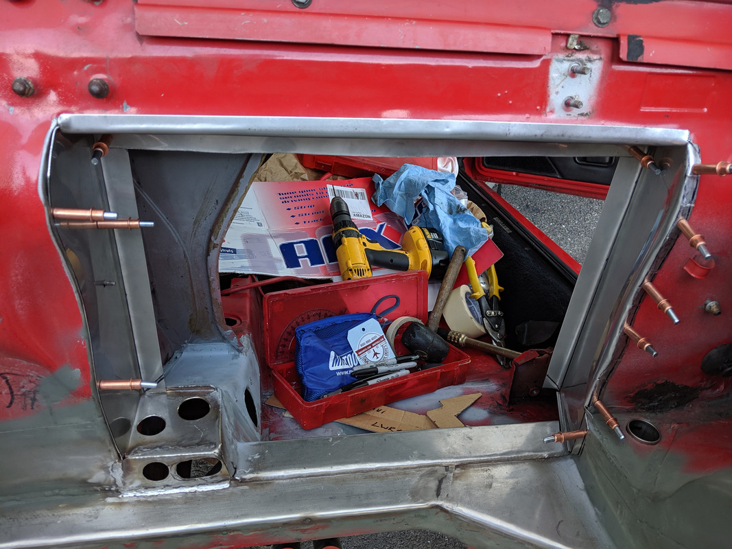
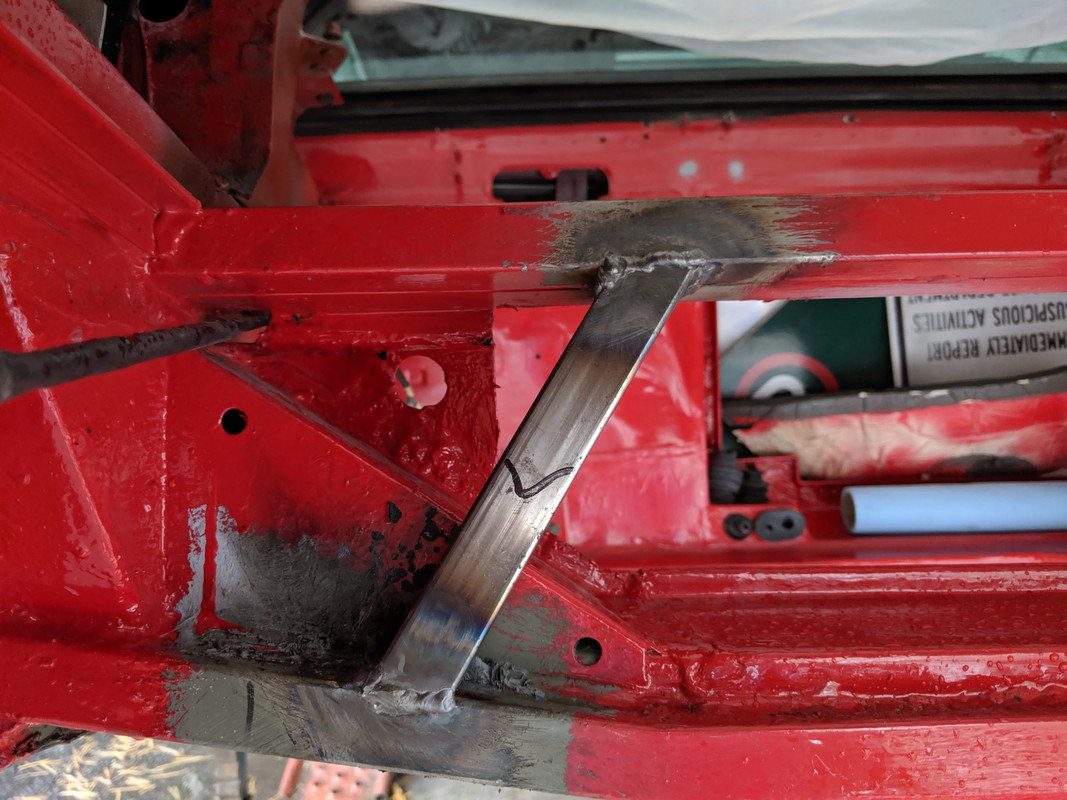
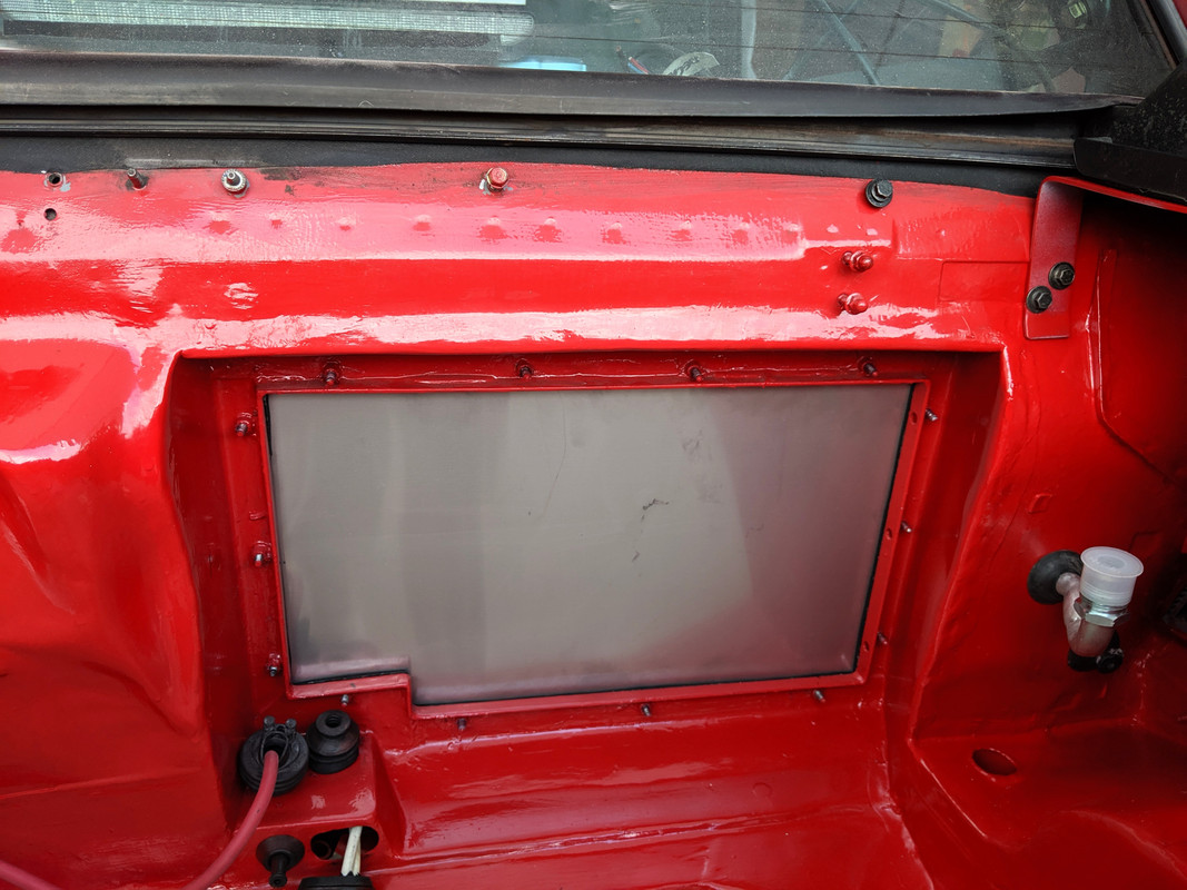
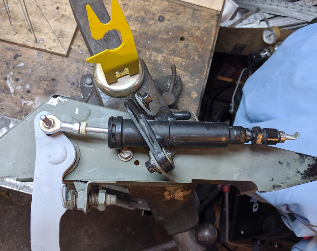
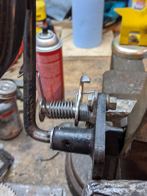
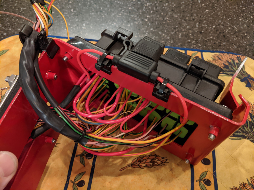
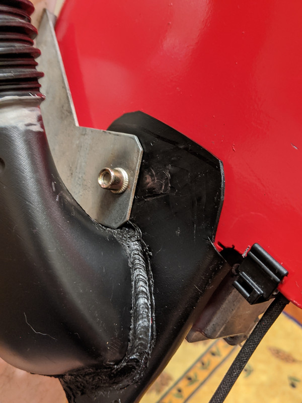
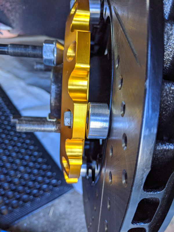
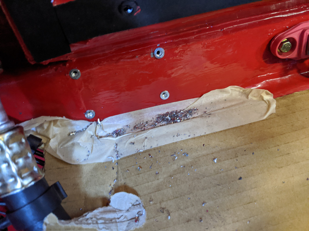
I bent the left tab flat & cut off some extra material to leave two flats I could drill for studs
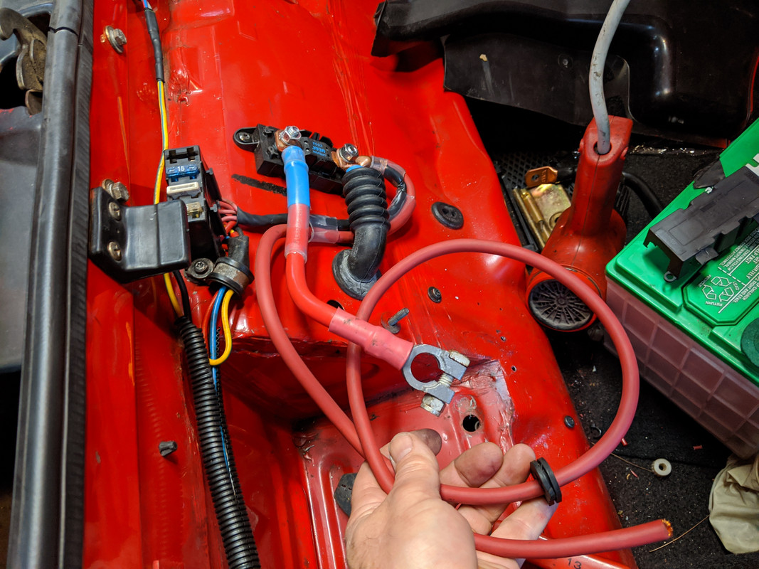
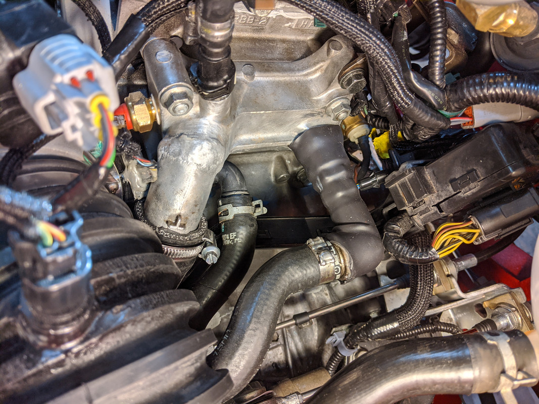
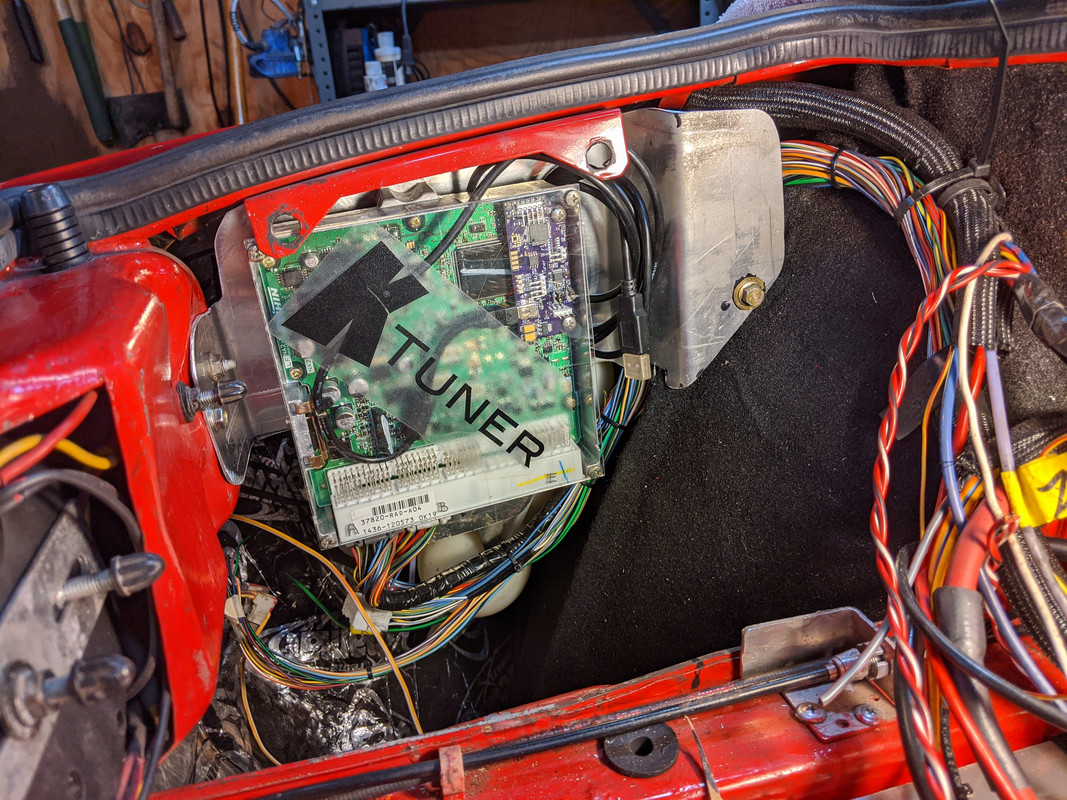
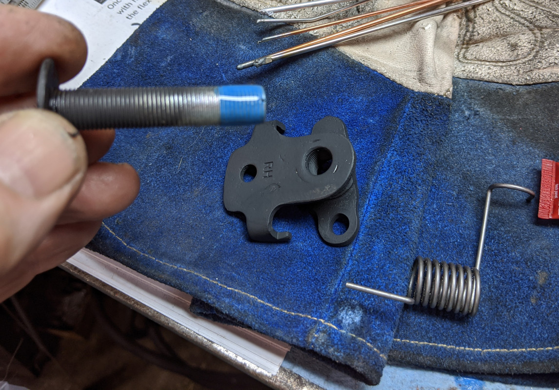
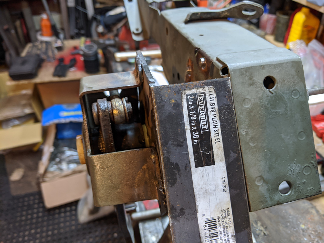
ELD module I/O to be addressed. For the trigger, I'm going to use the wire I had intended for the acfanrelay, since I've already run that from the trunk through to the Fiat fuse panel, so an easy extension out to the frunk from there. Other two are just switched power & ground.
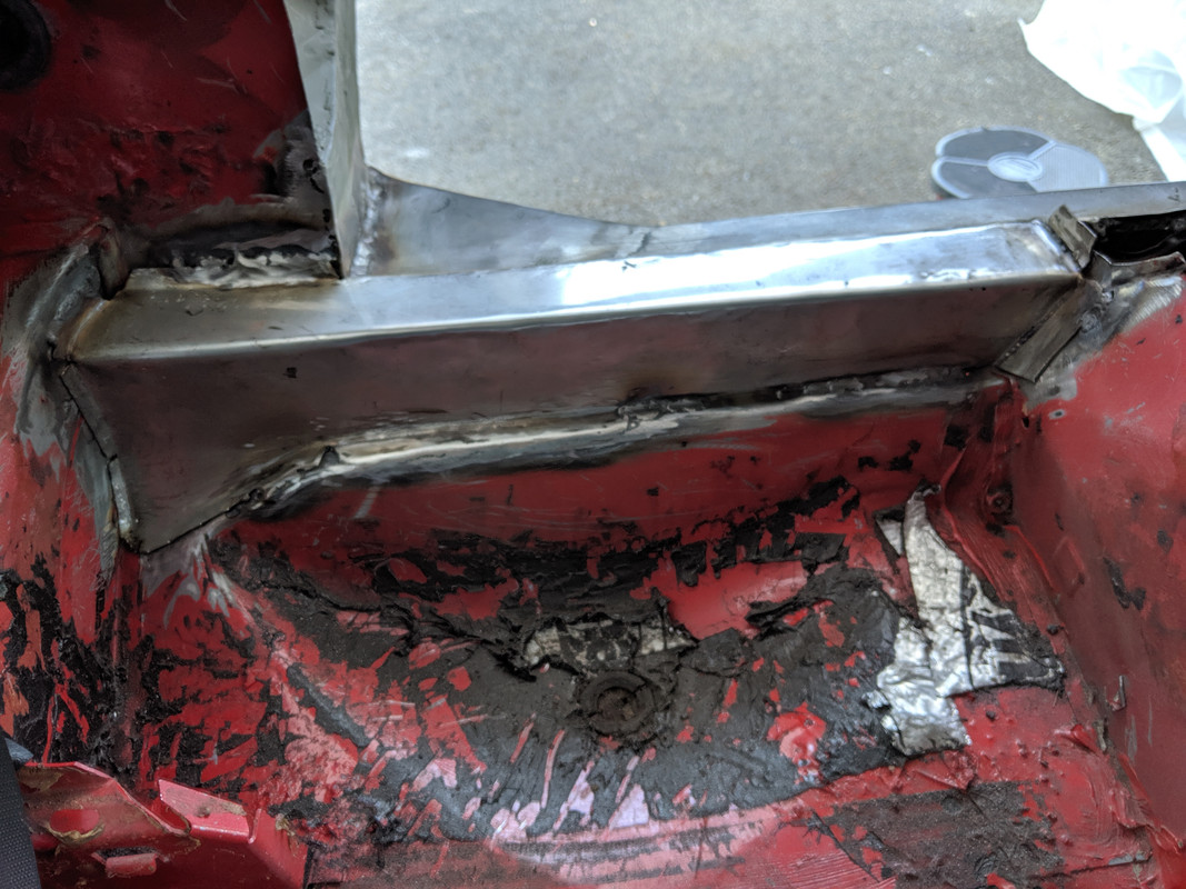
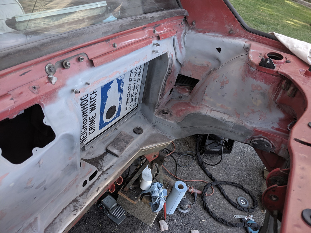
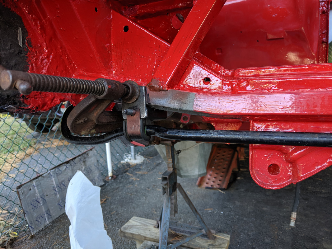
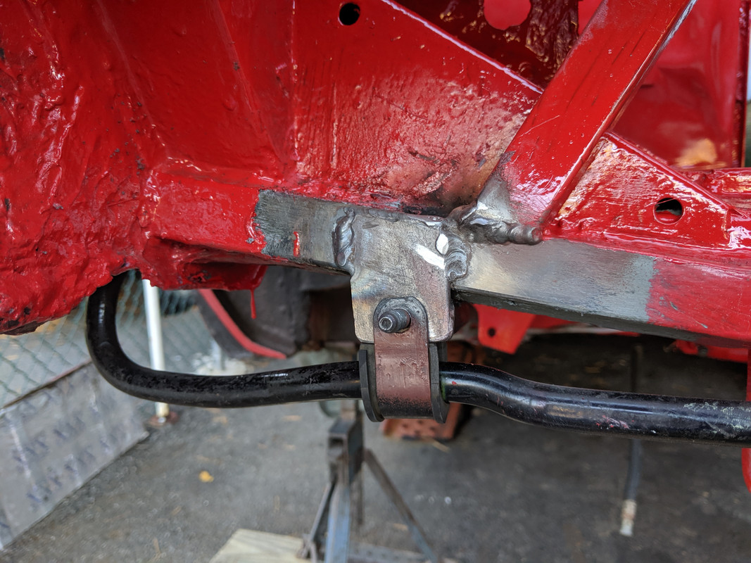
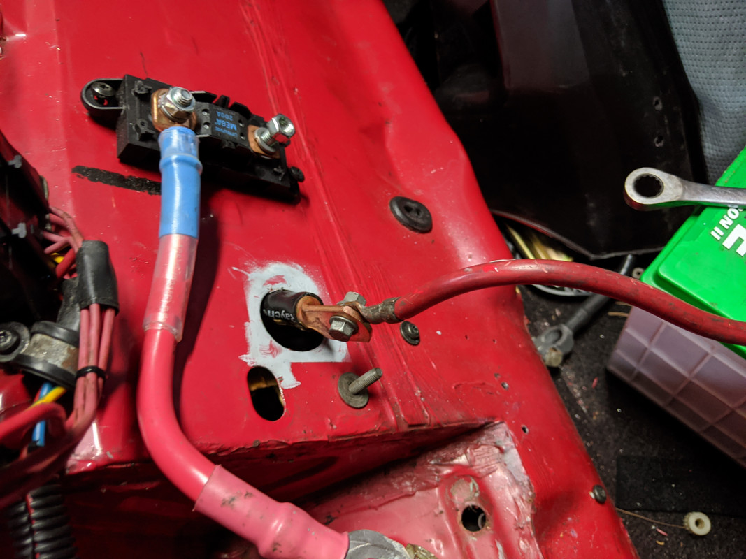
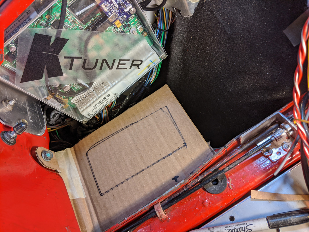
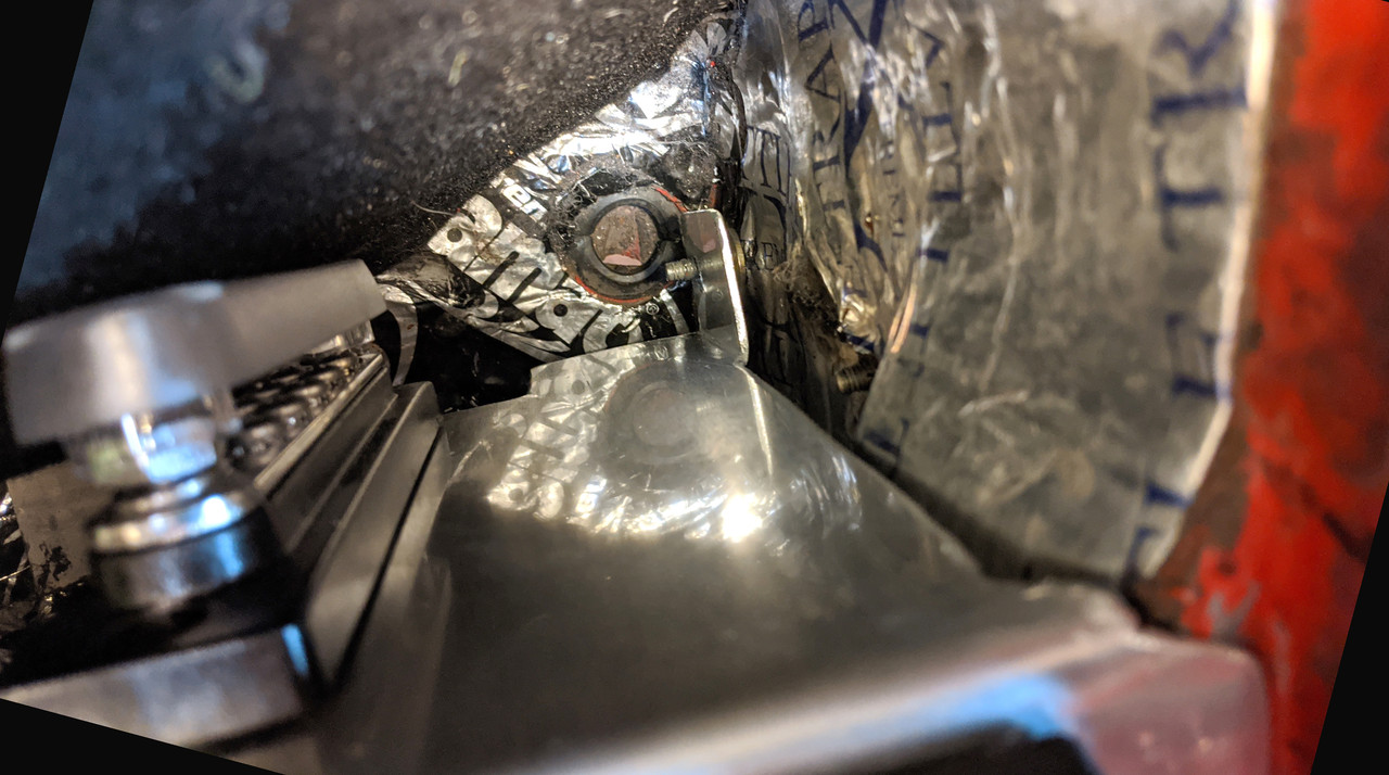
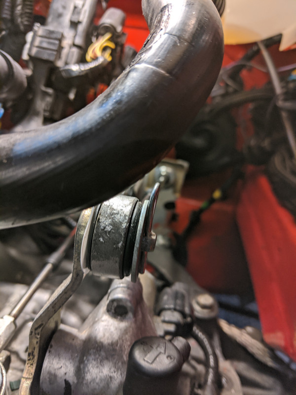
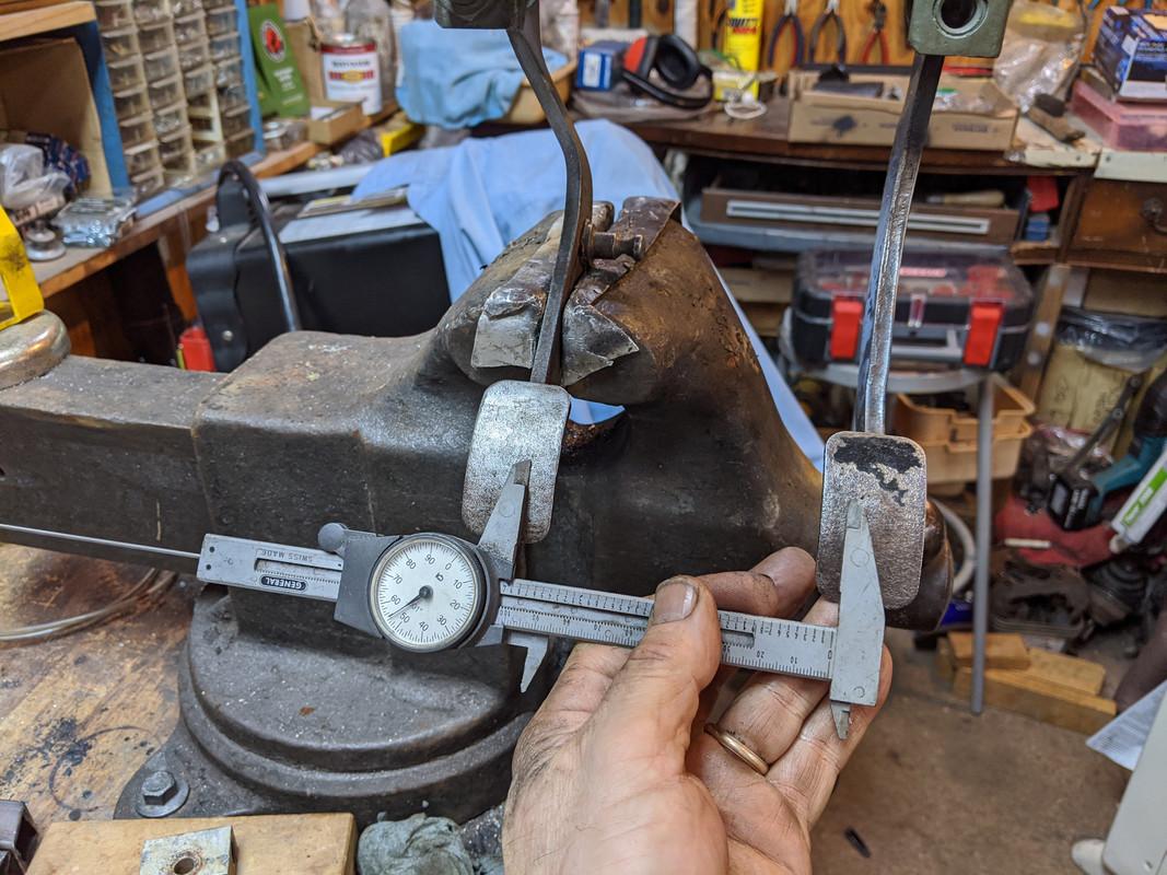
it will go between the battery cable & my inline fuse
looks like it will be OK. Will need some sort off insulation/isolation on the underside of the left left for safety.
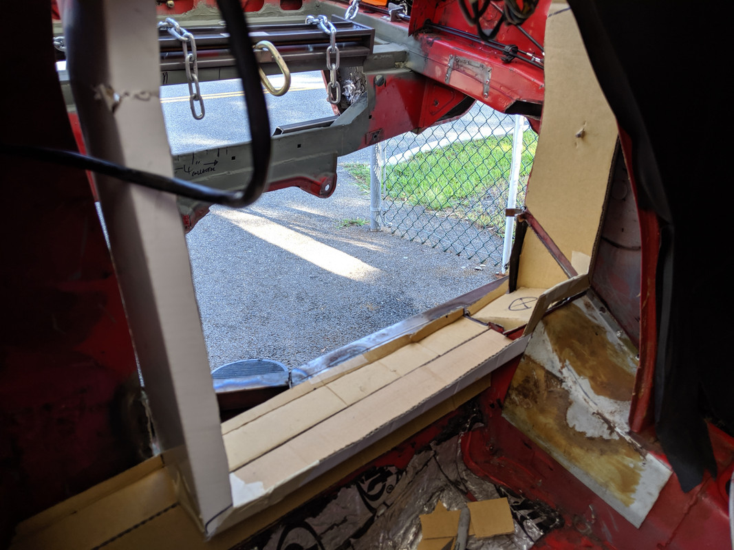
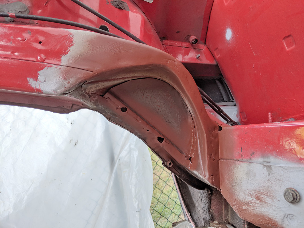
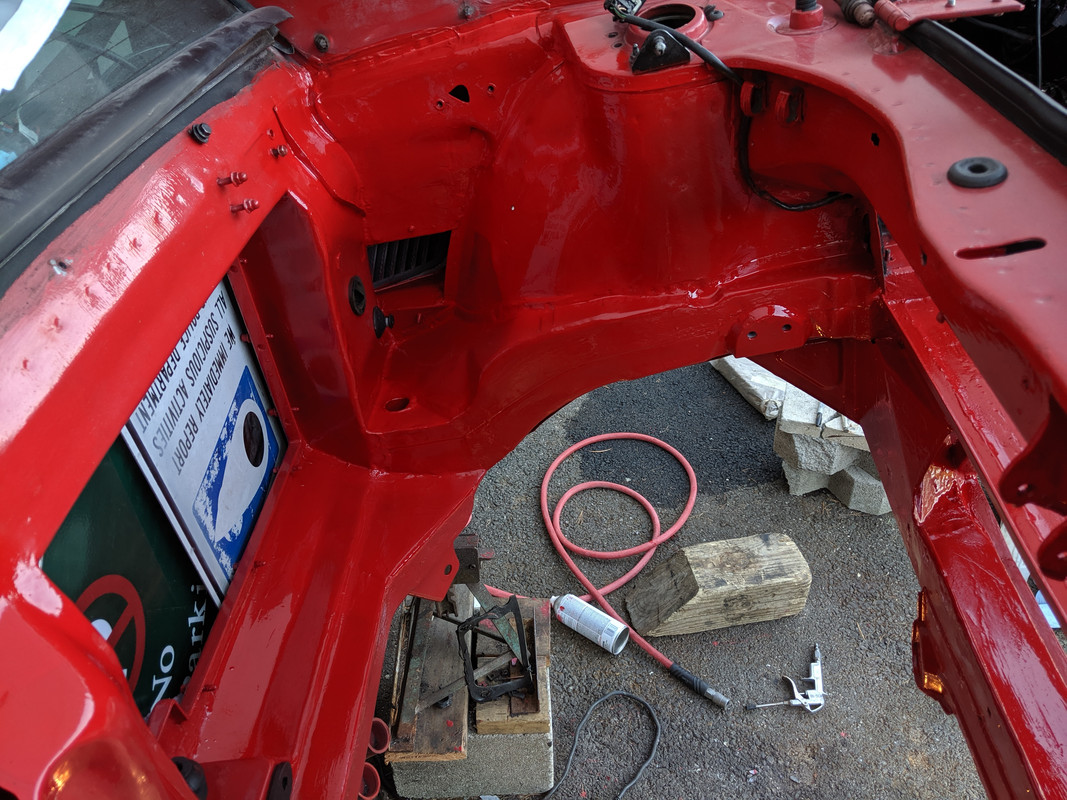
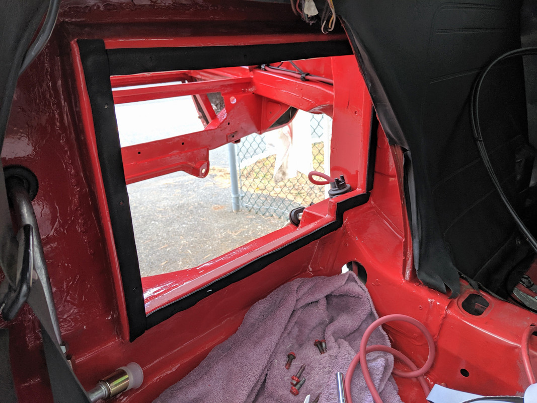
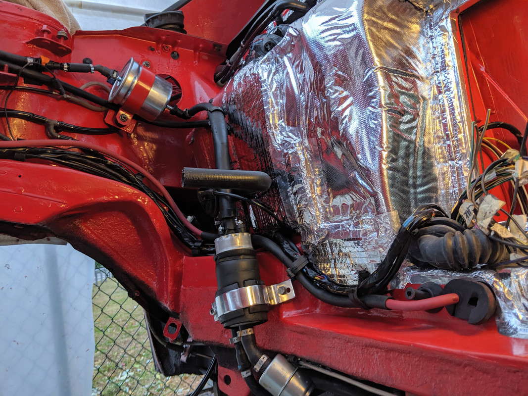
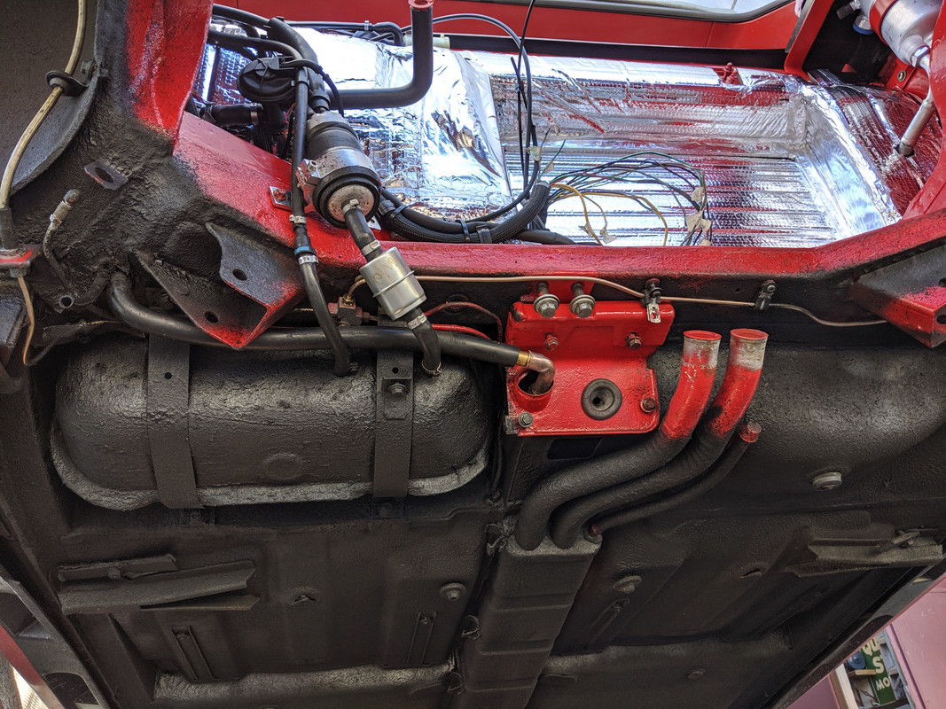
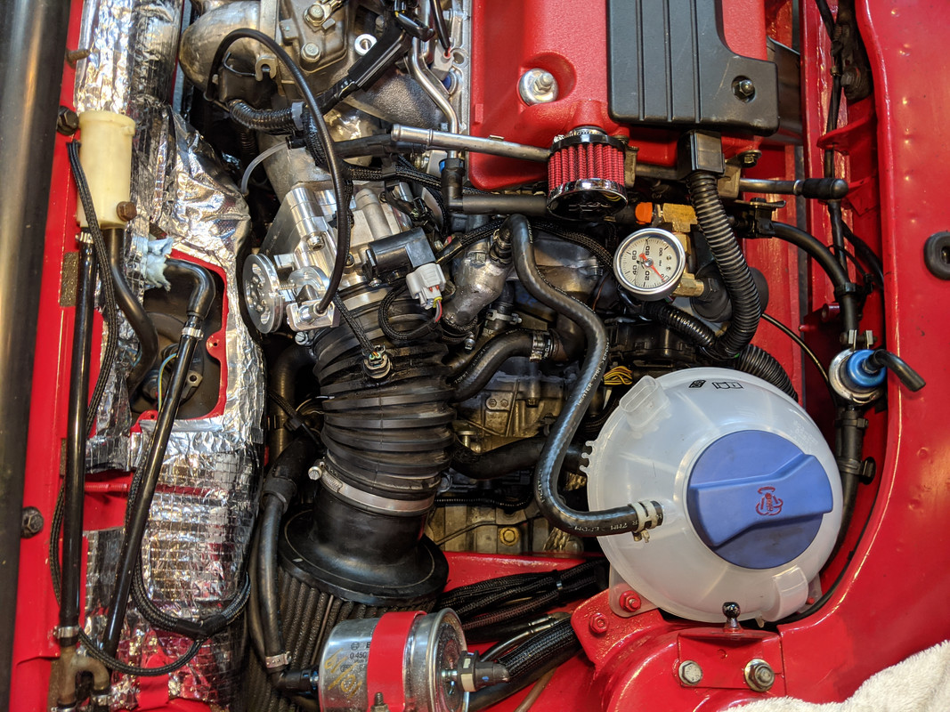
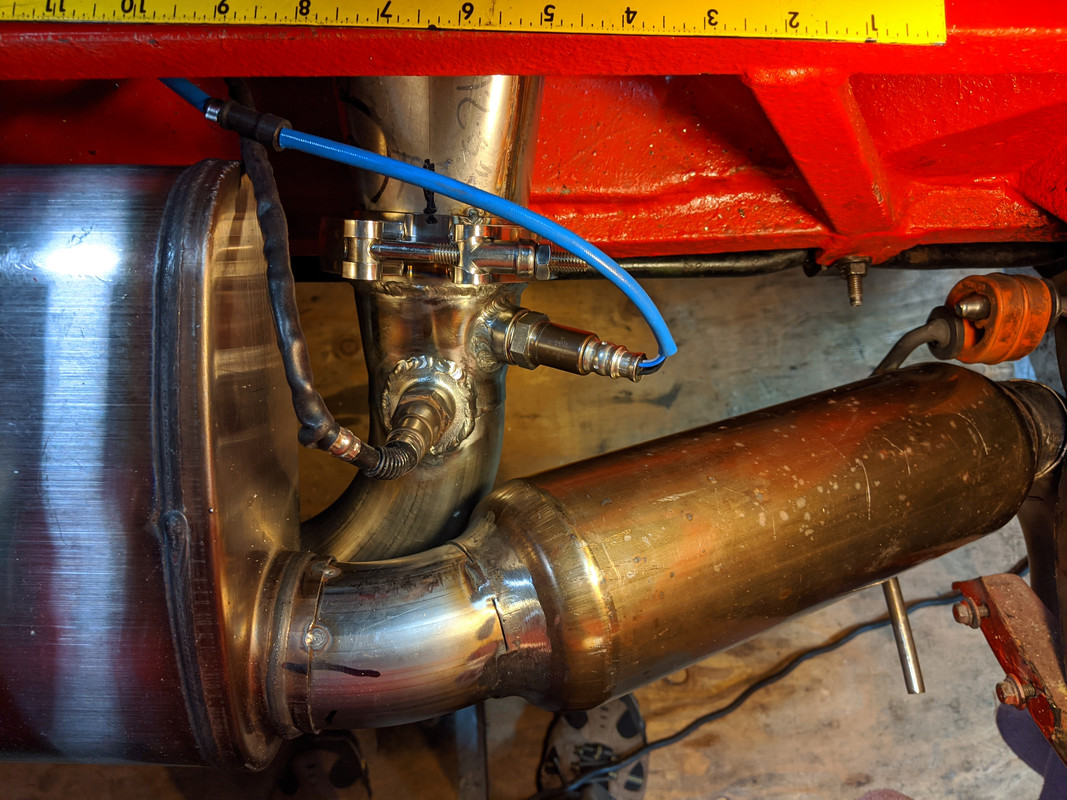
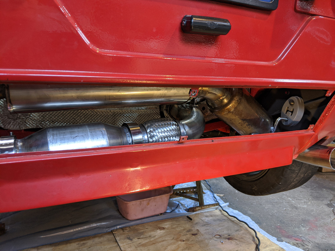
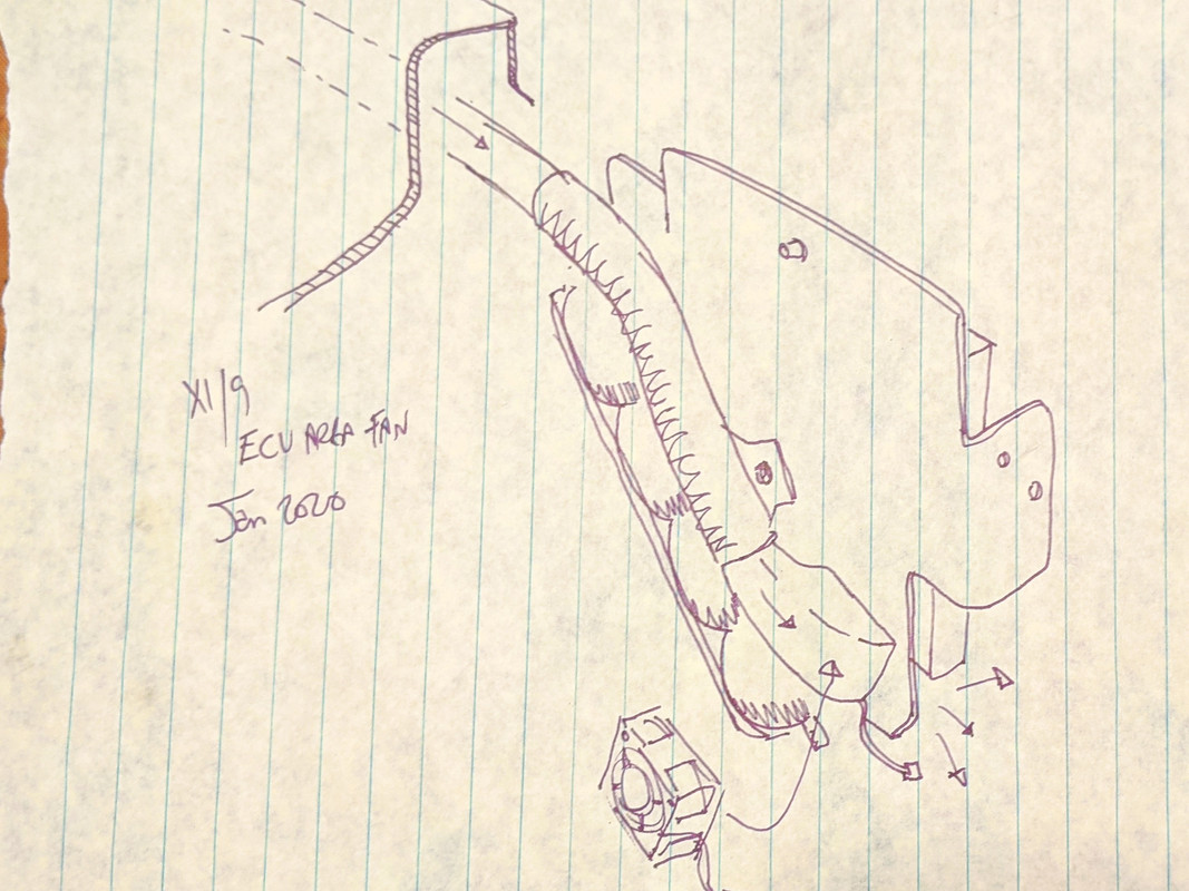
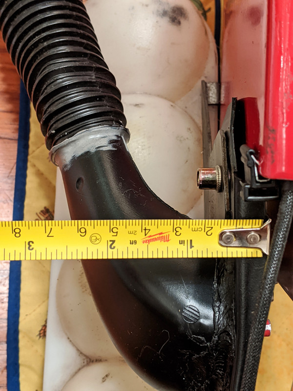
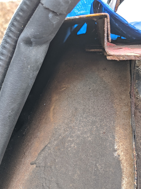
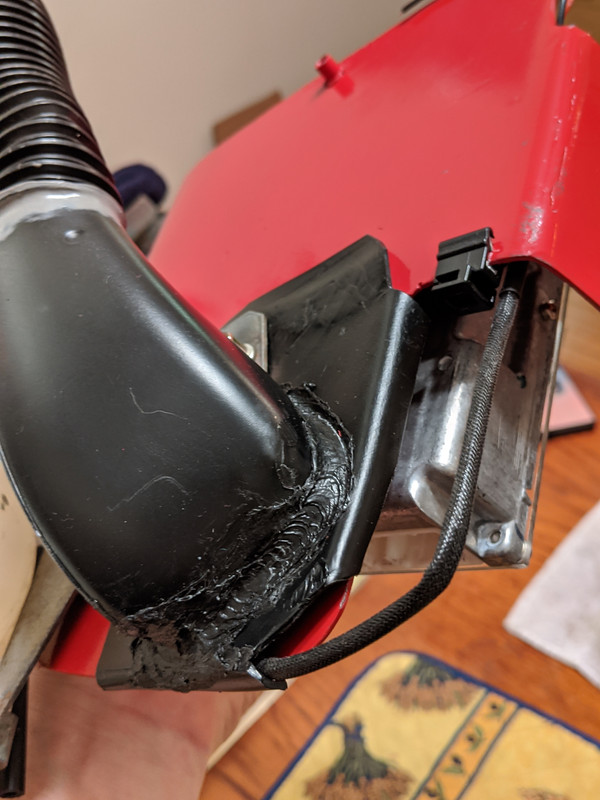
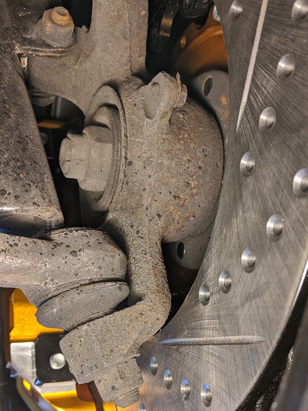
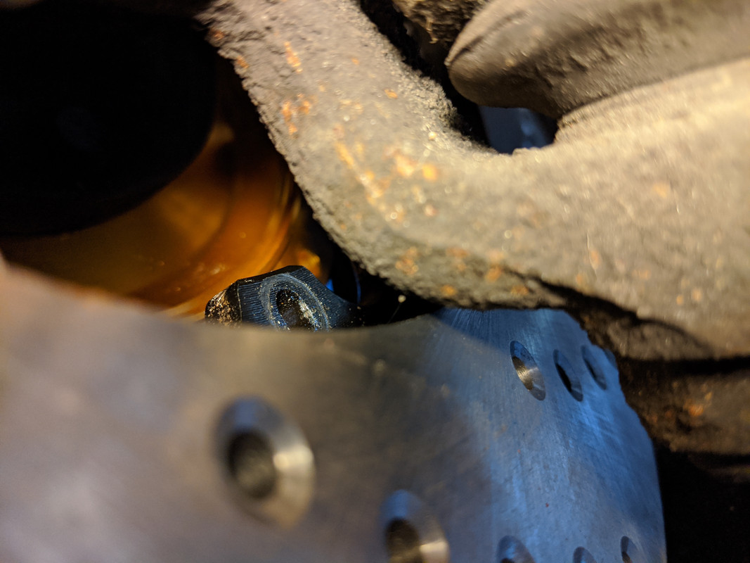
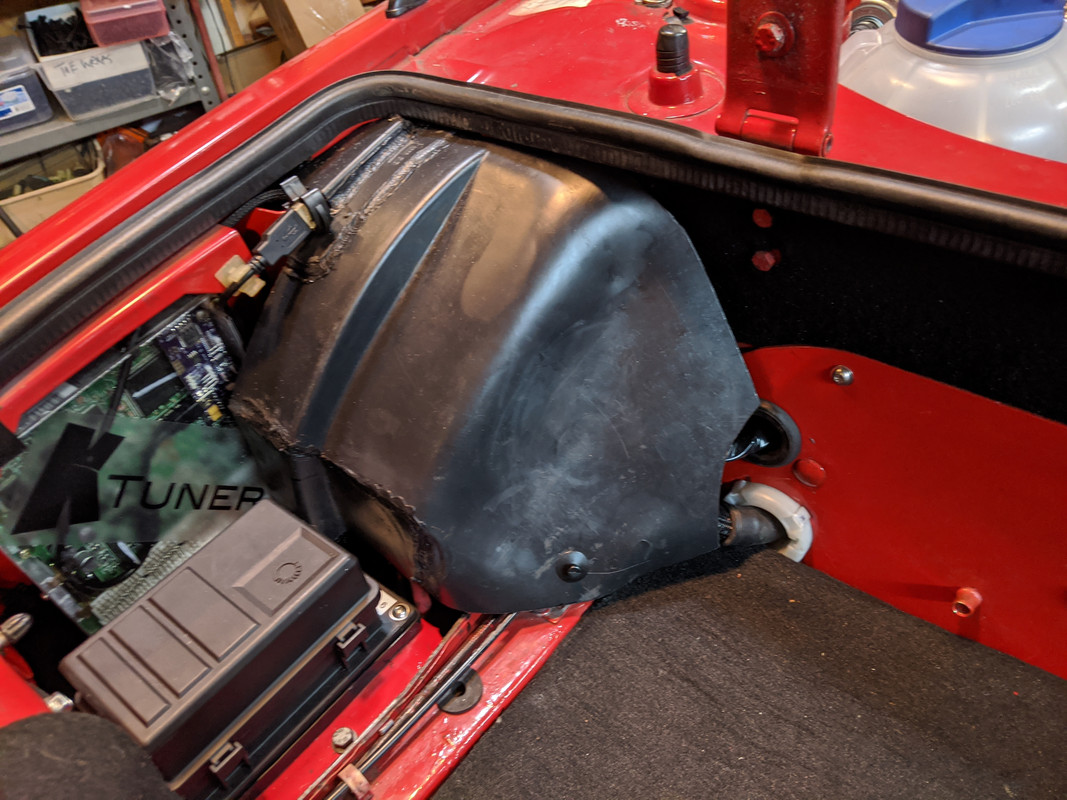
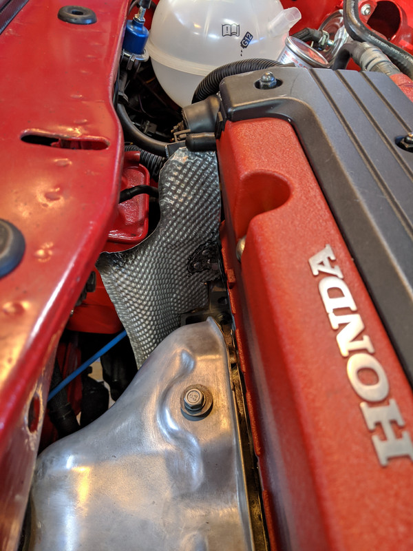
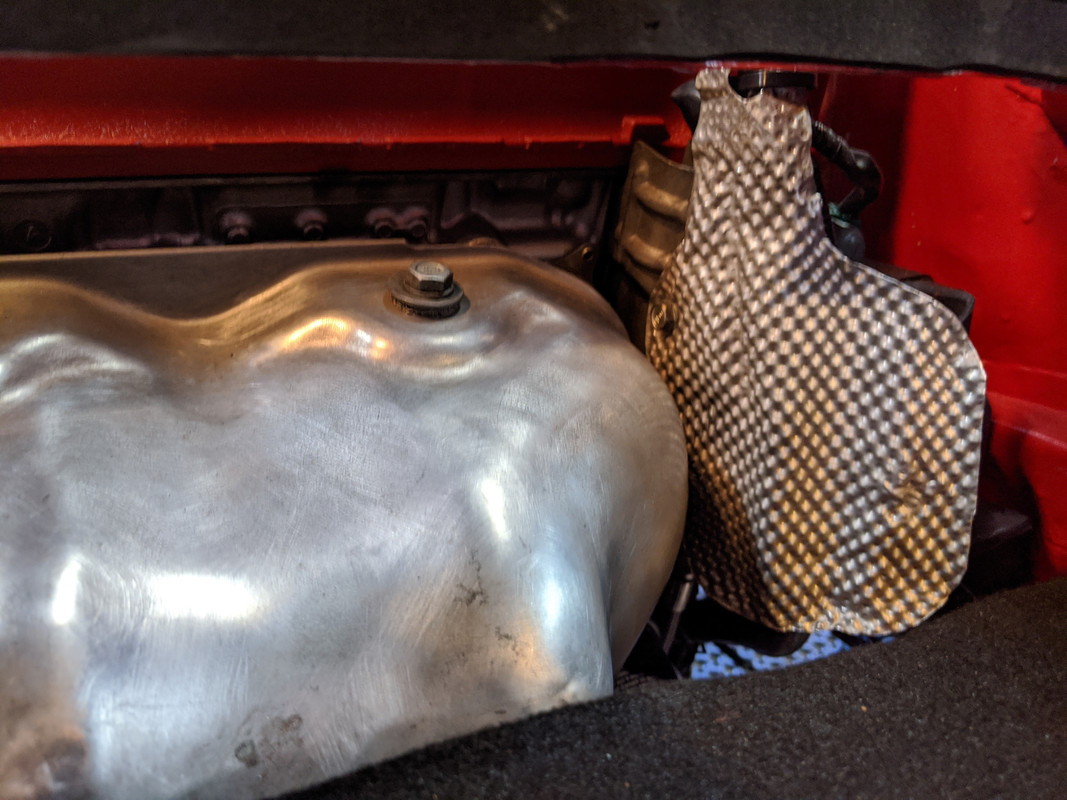
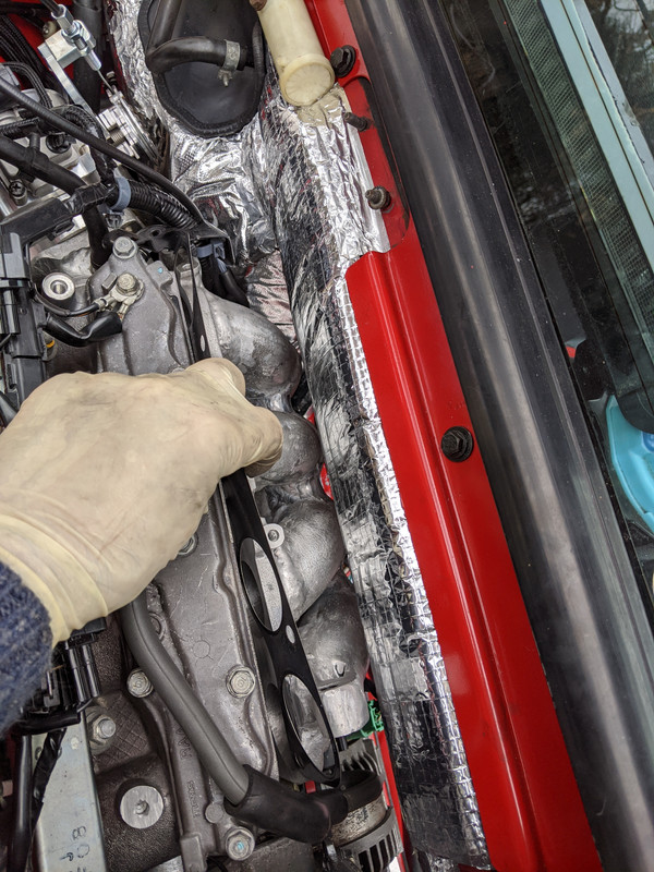
I shoved the duct hose into the inner fender, and found that the most I can get is about 14" forward - there is an reinforcing member below the targa sail that intersects with the inner fender & blocks further passage. Should be OK, still will be drawing air coming from either the gas tank well side opening or from the targa sail vent, I reckon