
the poi
Has been
- Joined
- Jan 5, 2003
- Location
- Pasadena, CA
Why?
960's are really slow, thats why. I'm slapping a turbo on mine and Megasquirting it. This means Motronic is out, along with its coded load signal and various torque limiting response commands. The stock transmission controller being as nervous as it is, won't enjoy working without the motronic box, and I didn't really feel like spending a lot of time analyzing the signals simply to replicate stock performance.
So, the obvious solutions is hijackign the electronic controls that cause the problems in the first place, and shift it manually. Naturally, flappy paddles will be the ideal control mechanism.
Also, they look rockin'.
Why not a manual?
Two major reasons: I live in LA, and I like brake boosting. Most people will never understand the concept of LA traffic without actually living here. The idea of pushing in and out on a clutch pedal for literally an hour without ever touching the stick is an experience I'd rather avoid. And as far as brake boosting goes: this car is going to see a lot more drag-strip time than road racing time, and being able to leave the line with a few pounds of boost is something I like.
The other problem is the cost. I don't want to spend a grand or so to get an M90 over here and install it, and get something I wasn't really looking for in the first place.
And hey, how many people have paddle-shifted a 960, eh?
What needs to be done...
Cooling
If I take over the TCM's controls, the lockup clutch will no longer be constantly popping on and off to control heat production of the relatively high stall TC (2700 rpm). Also, when decellerating or bogging the motor in heavy traffic, it's going to heat up, and I'd like capacity to cool it down and a way to keep an eye on it.
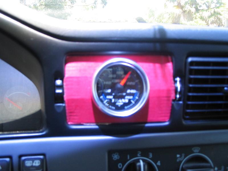
Lets start with the gauge, and AutoMeter Cobalt trans temp. It's purdy! (and won't be alone for long). Here's a horrible looking picture in its equally horrible looking temporary mount (sharp-eyed readers will note that that is the box it came in )
)
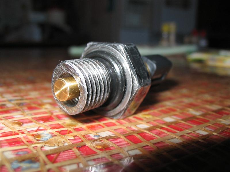
Fantastic, now where do we put the probe? The stock location would be the best, right on the exit to the cooler, the hottest point. Should be easy too. Here's how to install it:
Get a 14mm bolt, and chop it down so its short. Drill a hole in its middle and tap for the 1/8NPT thread that's on the autometer sensor. Screw the sensor in real good, and yoink the o-ring off the stock sensor.
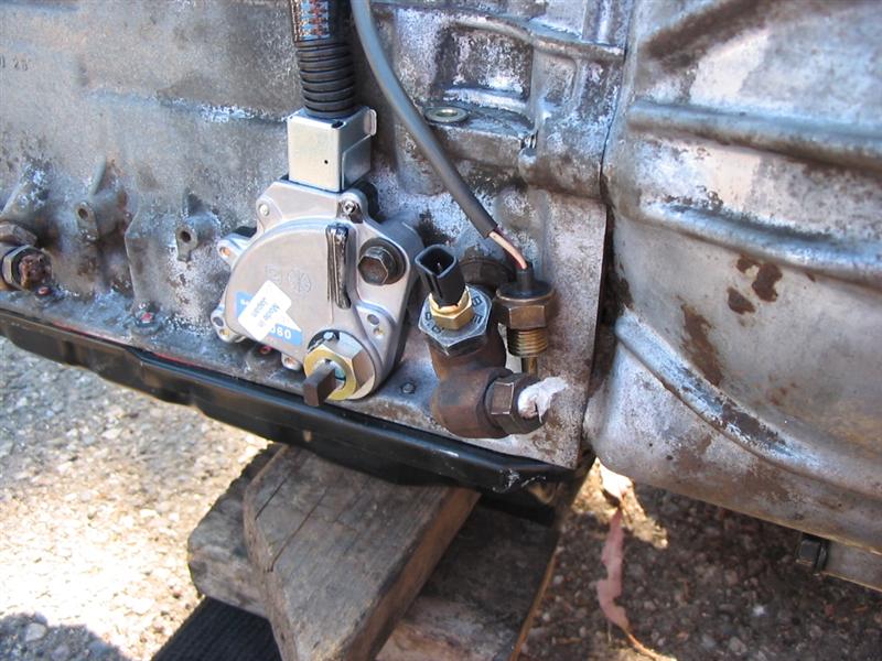
Now screw onto the fancy adapter Volvo uses that the stock sensor T's into:
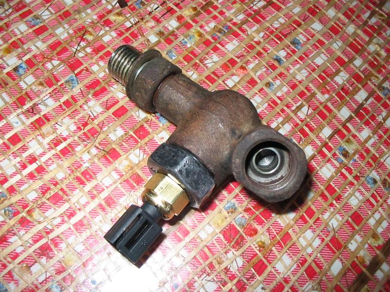
Here it's installed with the stock sensor hanging forlorn next to it, cleary upset at its removal:
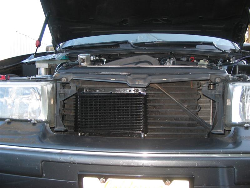
Now that that's taken care of, lets put in the biggest B&M trans cooler Jeg's sells. Here's a nice spot for it:
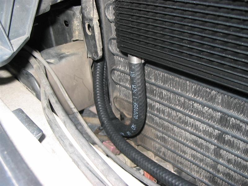
Route the rubber lines that come with the kit through the hole conveniently left from aw71 days:
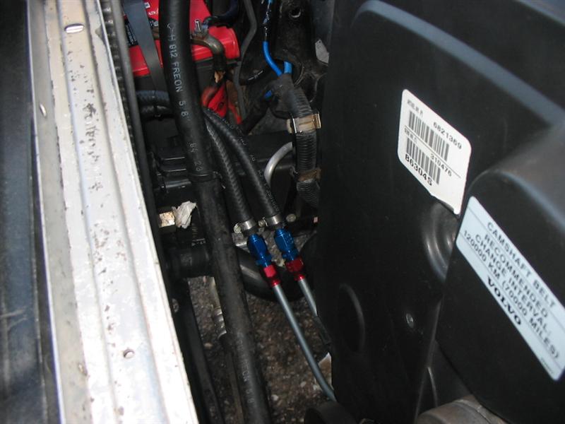
And connect them to some shiny AN fittings. There's two here, a 6AN to hose barb fitting, connected to a 6an to 3/8" tube fitting. These use compression fittings, so it's a matter of cutting the tube cleanly and clamping the fitting on.
Speaking of that tubing... Go down to NAPA, spend 15$ on two 3/8" 5ft lengths, and get to work with your bare hands and a cheap tubing bender. Here's how I fit mine. Re-using stock lines won't be the best for turbo projects, as stock, they come flying up from under the car and go straight through the prime turbo real estate before dropping to the radiator. Pretty dumb really.
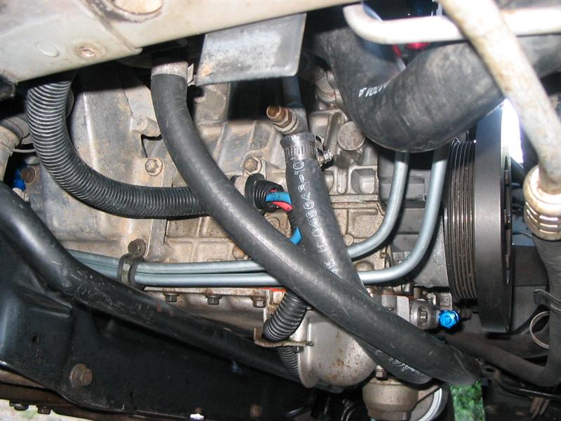
And finally, the trans. I re-used the metric flare fittings, just slipped them over the cut end of the lines (make sure to do this before you start bending ) and they seat against the flares that come on the lines. With the pre-flared lines and the compression type AN fittings on the other end, you don't have to hand-flare a thing!
The electronics!
This is where the fun happens! First, gotta figure out how you want it to behave. I settled on slapping the paddles from 1st to 4th and another "upshift" will engage the lockup clutch in thr torque converter for cruising. The line pressure solenoid will be left disconnected, meaning line pressure will be maxed. This will probably mean harsher reverse and drive engagement, but it shouldn't hurt anything and it will save me a hell of a lot of development.
I was starting from scratch, so I needed to start with some manuals. Thanks to tjts1 (who I generally refer to as "tits" cause really thats what it looks like) I got this helpful info straight from Volvo: http://caunter.ca/volvo960/ce14807.pdf . So the control algortithm is pretty simple:
With the PNP switch not in a "Drive" mode, set to 1st gear. In a drive mode (D,3,L), turn on the paddles. Set the shift solenoids as needed for each gear. Pretty simple algorithm.
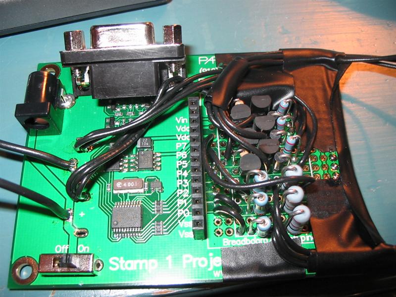
But how to get that to happen? I looked into using basic components and IC's (counters and the like) but it was pretty much over my head, and I realized that this is the perfect project for a microcontroller. So thats what I got, in the form of a BASIC Stamp from www.parallax.com . I've heard of stamps before, never used one before though. The code is really easy to use though, and within a couple hours of downloading the compiler, I had the controller code roughed out.
Here's what I eventually came up with:
And a short vid showing how the solenoids work with each shift: < Dead! >
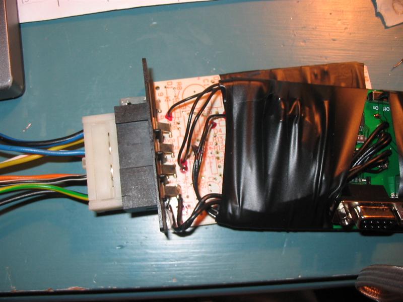
Now, the outputs are controlled by logic level outputs, so I need to step up the power with some transistor switches. The tricky thing is that i need to send 12v to the solenoid, which requires a PNP/NPN circuit. Got some help from usegroups, and figured out the output circuit I needed to use for each of the solenoids.
edit:// I ended up switching the circuit to something a lot simpler. Just use high-side switch ICs, and just wire the output to the HSS input, and have at it. I used Infineon BTS409L1IN
The next challenge was managing to fit all the components onto the pretty limited proto-space on the Stamp project board... but I did get it, and put the whole thing in an attractive case.
The frickin paddles!
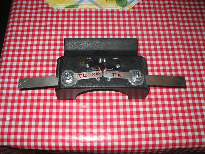
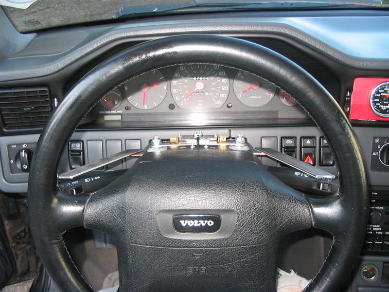
So now we need something to slap when we want the gear to change. I decided to mount the assembly fixed to the steering column (not the wheel)-- seems more comfortable to me, as I always know where the paddles are. Unfortunately, there is no room really in the plastic case around the column to fit much of any mechanism, so I had to figure out something else. After a failed attempt at moutning something on the bottom, and another failed attempt on the top when using simply the wrong hardware... I settled on this trippy in-line skate bearing voodoo:
Some description: The arms come out slots through the side, and are bolted to the bottom of the bearing. The actuator arms are on top (obviously). The nut is a ny-lock, and I slotted the bolt so i get hold it with a screwdriver while tighetening the nut. This lets me adjust the angle between the actuator arm and the paddle arm with the column completely installed.
I put the pivots out as far as possible and the buttons all the way in. This minimizes mechanical advantage, which reduces the throw of the paddle and makes it harder to pull (resulting in a snappy, quick, and positive pull).
The switches are NO microswitches that give a good positive click when actuated. The result of all of this makes for a very smooth actuation, with essentially no drag-related resistance.
Now we get to posistion the arms, which was a right bitch really. There's very little wiggle room with these things. You have to make sure both stalks still work, and the wheel doesn't contact anything during turns. After some time with cardboard models and a lot of swearing, I got this:
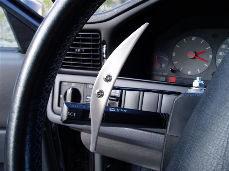
And now to make it all artistic and crap!
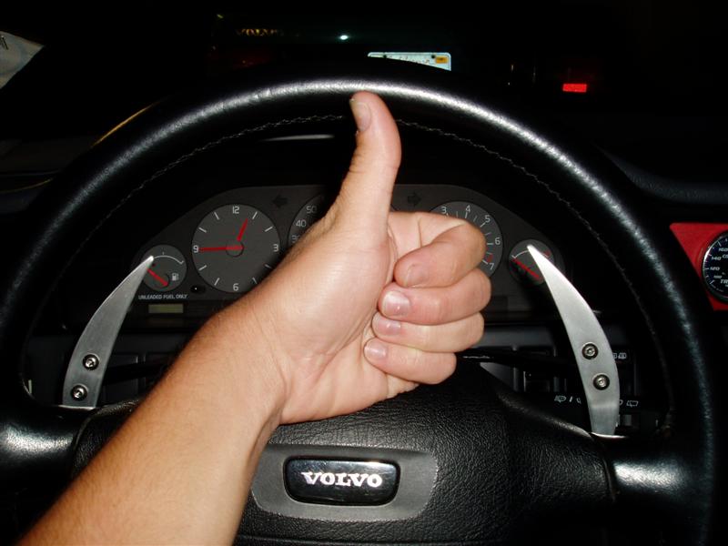
Here's what I came up with:
Rockin'.
The paddles came from Home Depot... sorta. Started as 3in by 3ft 1/8" aluminum. After some more cardboard models, I cut the rough shapes out with my angle grinder, filed down the edges, and got to work. I ground the edges round with a Dremel with a sanding roll, and finished them with a wetsanding from 100 to 400 to 600 grit. They look great, and aren't shiny so they won't blind you if they catch the sun right .
They're mounted with 10/32 SS cap screws, cut and smoothed flush with the mounting point.
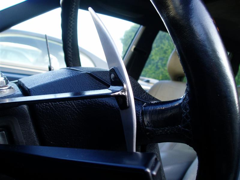
Those mounts were also kinda annoying. Had to weld em on with a MIG welder, and they're only about 3/4" . Once I got the welds down, I ground them smooth. Then the whole thing got sanded and painted with engine enamel. The holes are drilled and tapped to recieve the moutning bolts.
And that's that. Still need to figure out something to cover the mechanism. I have a good plastic case, but I think I'm going to want to incorporate some nice leather on it somehow...
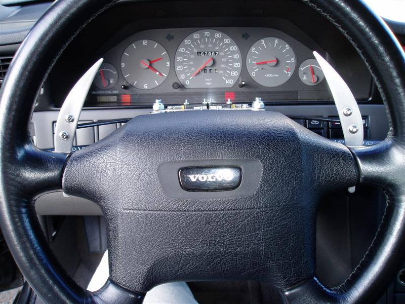
Some finished pics:
Well then... how's it work?!
It's ****ing fantastic.
I never knew you could have so much fun with a mere 200hp and 3700lbs of bulk It's just like a manual as far as putting it in the right gear, so it's pretty damn awesome. The shifts are as fast (as slow...) as full throttle shifts on the stock TCM, so theres a about a half second delay. I could "fix" this by shimming up the accumulators a bit... but I'm afraid of getting too greedy and breaking something. It's awesome as it stands though.
Highway driving is great: no traffic means leaving it in 4th+L, light traffic means a but of shifting between lockup and no lockup, but it's not a problem at all seeing as its just a tap of the paddle. Heavy traffic is way better than witht he auto, which seemed to always pick bad gears, and always making it lug around and making throttle response nonexistant before slamming it into third and shooting you foward. I can keep it in 3 and crawl along without having the annoying lug. Stop and go traffic is just as easy. Leave it in 1st, with the occasional slap into 2nd.
City driving is hilarious, and I'll probably end up with several tickets because of it. I'm probably burning through oil now seeing as I love keeping the big sewing machine at atleast 3 grand .
To conclude: **** ya.
edit:// ya ya, I'll get video sometime") My vid-capable camera is 100 miles away!
My vid-capable camera is 100 miles away!
960's are really slow, thats why. I'm slapping a turbo on mine and Megasquirting it. This means Motronic is out, along with its coded load signal and various torque limiting response commands. The stock transmission controller being as nervous as it is, won't enjoy working without the motronic box, and I didn't really feel like spending a lot of time analyzing the signals simply to replicate stock performance.
So, the obvious solutions is hijackign the electronic controls that cause the problems in the first place, and shift it manually. Naturally, flappy paddles will be the ideal control mechanism.
Also, they look rockin'.
Why not a manual?
Two major reasons: I live in LA, and I like brake boosting. Most people will never understand the concept of LA traffic without actually living here. The idea of pushing in and out on a clutch pedal for literally an hour without ever touching the stick is an experience I'd rather avoid. And as far as brake boosting goes: this car is going to see a lot more drag-strip time than road racing time, and being able to leave the line with a few pounds of boost is something I like.
The other problem is the cost. I don't want to spend a grand or so to get an M90 over here and install it, and get something I wasn't really looking for in the first place.
And hey, how many people have paddle-shifted a 960, eh?
What needs to be done...
Cooling
If I take over the TCM's controls, the lockup clutch will no longer be constantly popping on and off to control heat production of the relatively high stall TC (2700 rpm). Also, when decellerating or bogging the motor in heavy traffic, it's going to heat up, and I'd like capacity to cool it down and a way to keep an eye on it.
Lets start with the gauge, and AutoMeter Cobalt trans temp. It's purdy! (and won't be alone for long). Here's a horrible looking picture in its equally horrible looking temporary mount (sharp-eyed readers will note that that is the box it came in
)
Fantastic, now where do we put the probe? The stock location would be the best, right on the exit to the cooler, the hottest point. Should be easy too. Here's how to install it:
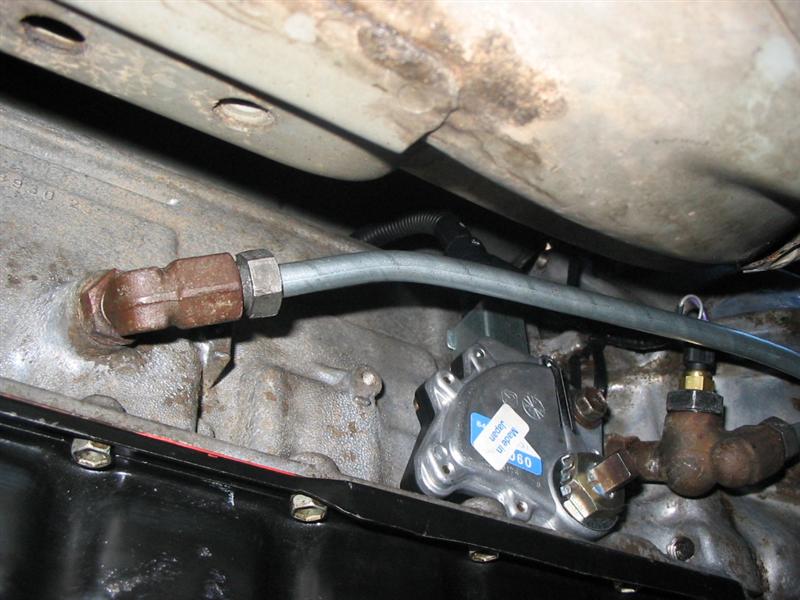
Get a 14mm bolt, and chop it down so its short. Drill a hole in its middle and tap for the 1/8NPT thread that's on the autometer sensor. Screw the sensor in real good, and yoink the o-ring off the stock sensor.
Now screw onto the fancy adapter Volvo uses that the stock sensor T's into:
Here it's installed with the stock sensor hanging forlorn next to it, cleary upset at its removal:
Now that that's taken care of, lets put in the biggest B&M trans cooler Jeg's sells. Here's a nice spot for it:
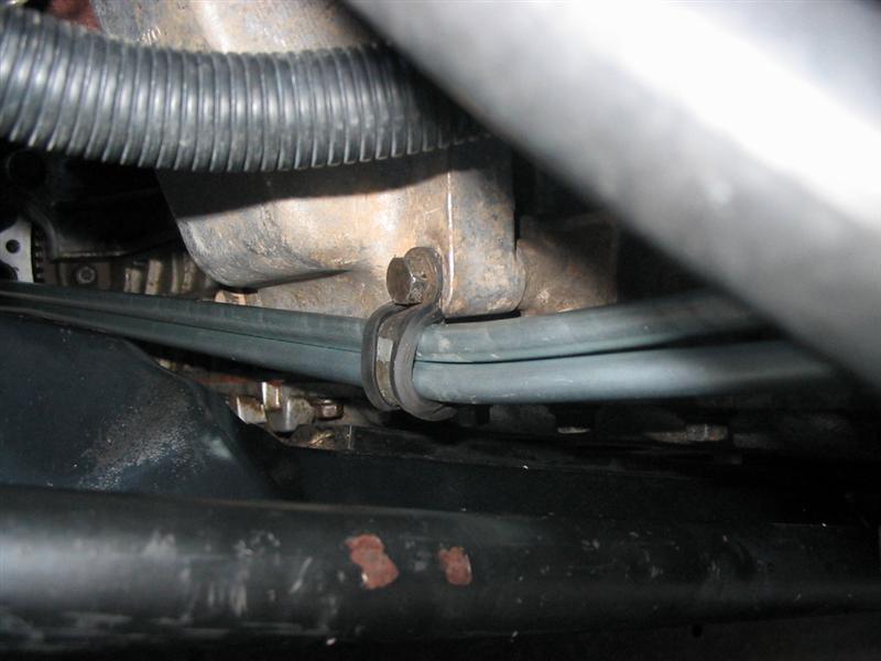
Route the rubber lines that come with the kit through the hole conveniently left from aw71 days:
And connect them to some shiny AN fittings. There's two here, a 6AN to hose barb fitting, connected to a 6an to 3/8" tube fitting. These use compression fittings, so it's a matter of cutting the tube cleanly and clamping the fitting on.
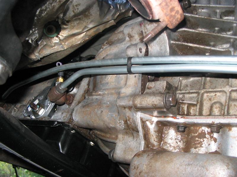
Speaking of that tubing... Go down to NAPA, spend 15$ on two 3/8" 5ft lengths, and get to work with your bare hands and a cheap tubing bender. Here's how I fit mine. Re-using stock lines won't be the best for turbo projects, as stock, they come flying up from under the car and go straight through the prime turbo real estate before dropping to the radiator. Pretty dumb really.
And finally, the trans. I re-used the metric flare fittings, just slipped them over the cut end of the lines (make sure to do this before you start bending
) and they seat against the flares that come on the lines. With the pre-flared lines and the compression type AN fittings on the other end, you don't have to hand-flare a thing!
The electronics!
This is where the fun happens! First, gotta figure out how you want it to behave. I settled on slapping the paddles from 1st to 4th and another "upshift" will engage the lockup clutch in thr torque converter for cruising. The line pressure solenoid will be left disconnected, meaning line pressure will be maxed. This will probably mean harsher reverse and drive engagement, but it shouldn't hurt anything and it will save me a hell of a lot of development.
I was starting from scratch, so I needed to start with some manuals. Thanks to tjts1 (who I generally refer to as "tits" cause really thats what it looks like) I got this helpful info straight from Volvo: http://caunter.ca/volvo960/ce14807.pdf . So the control algortithm is pretty simple:
With the PNP switch not in a "Drive" mode, set to 1st gear. In a drive mode (D,3,L), turn on the paddles. Set the shift solenoids as needed for each gear. Pretty simple algorithm.
But how to get that to happen? I looked into using basic components and IC's (counters and the like) but it was pretty much over my head, and I realized that this is the perfect project for a microcontroller. So thats what I got, in the form of a BASIC Stamp from www.parallax.com . I've heard of stamps before, never used one before though. The code is really easy to use though, and within a couple hours of downloading the compiler, I had the controller code roughed out.
Here's what I eventually came up with:
Code:
' {$STAMP BS1}
' {$PBASIC 1.1}

'The Poi's (Chris Wiita's) AW30-40 paddle shifter code
'v1.1

'I/Os:
' 0  is Upshift button input - set to input with BUTTON function
' 1  is Downshift button input - set to input with BUTTON function

' 2  is Solenoid 1 - engages when 1
' 3  is Solenoid 2 - engages when 1
' 4  is Lockup Solenoid - engages when 1

' 5  is Ground for "drive" funcitons of PNP switch.  When grounded, flappy
'       paddles work.  Whenever it loses ground, switches back to 1st

'Shift Table:
'  Gear    Sol1     Sol2    TCC
'    1       1       0       0
'    2       1       1       0
'    3       0       1       0
'    4       0       0       0
'  4+TCC     0       0       1

' "1st Gear" for P N and R.


SYMBOL        Gear        = B0  'Current gear

SYMBOL        UpBtnWrk   = B2
SYMBOL        DwnBtnWrk  = B3
SYMBOL        DriveBtnWrk= B4

UpBtnWrk = 0
DwnBtnWrk = 0
DriveBtnWrk = 0

'Start in first gear
Gear = 1
GOTO SetGear

'Start loop by checking that PNP is in drive mode, if its grounded, start loop,
'otherwise, set gear to 1, keep checking till drive
ChkDriveBtn:
BUTTON 5,0,255,0,DriveBtnWrk,1,Go
PAUSE 100
BUTTON 5,0,255,0,DriveBtnWrk,1,Go
Gear = 1
GOTO SetGear

'Clear button work so it keeps checking if its down, chk upbtn
Go:
DriveBtnWrk = 0
GOTO ChkUpBtn

'Check up button, if grounded, upshift, else, check down button
ChkUpBtn:
BUTTON 0,0,255,0,UpBtnWrk,1,UpShift
GOTO ChkDwnBtn

UpShift:
Gear = Gear + 1
GOTO SetGear

'Check down button, if grounded, downshift, else, check drive button
ChkDwnBtn:
BUTTON 1,0,255,0,DwnBtnWrk,1,DownShift
GOTO ChkDriveBtn

DownShift:
Gear = Gear - 1
GOTO SetGear


SetGear:
BRANCH Gear, (SetGear0,SetGear1,SetGear2,SetGear3,SetGear4,SetGear5,SetGear6)

SetGear0:
Gear = 1
GOTO ChkDriveBtn

SetGear1:
LOW 4   'Lockup
HIGH 2  'Sol1
LOW 3   'Sol2
GOTO ChkDriveBtn

SetGear2:
LOW 4   'Lockup
HIGH 2  'Sol1
HIGH 3  'Sol2
GOTO ChkDriveBtn

SetGear3:
LOW 4   'Lockup
LOW 2   'Sol1
HIGH 3  'Sol2
GOTO ChkDriveBtn

SetGear4:
LOW 4   'Lockup
LOW 2   'Sol1
LOW 3   'Sol2
GOTO ChkDriveBtn

SetGear5:
HIGH 4  'Lockup
LOW 2   'Sol1
LOW 3   'Sol2
GOTO ChkDriveBtn

SetGear6:
Gear = 5
GOTO ChkDriveBtn
And a short vid showing how the solenoids work with each shift: < Dead! >
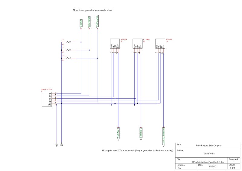
Now, the outputs are controlled by logic level outputs, so I need to step up the power with some transistor switches. The tricky thing is that i need to send 12v to the solenoid, which requires a PNP/NPN circuit. Got some help from usegroups, and figured out the output circuit I needed to use for each of the solenoids.
edit:// I ended up switching the circuit to something a lot simpler. Just use high-side switch ICs, and just wire the output to the HSS input, and have at it. I used Infineon BTS409L1IN
The next challenge was managing to fit all the components onto the pretty limited proto-space on the Stamp project board... but I did get it, and put the whole thing in an attractive case.
The frickin paddles!
So now we need something to slap when we want the gear to change. I decided to mount the assembly fixed to the steering column (not the wheel)-- seems more comfortable to me, as I always know where the paddles are. Unfortunately, there is no room really in the plastic case around the column to fit much of any mechanism, so I had to figure out something else. After a failed attempt at moutning something on the bottom, and another failed attempt on the top when using simply the wrong hardware... I settled on this trippy in-line skate bearing voodoo:
Some description: The arms come out slots through the side, and are bolted to the bottom of the bearing. The actuator arms are on top (obviously). The nut is a ny-lock, and I slotted the bolt so i get hold it with a screwdriver while tighetening the nut. This lets me adjust the angle between the actuator arm and the paddle arm with the column completely installed.
I put the pivots out as far as possible and the buttons all the way in. This minimizes mechanical advantage, which reduces the throw of the paddle and makes it harder to pull (resulting in a snappy, quick, and positive pull).
The switches are NO microswitches that give a good positive click when actuated. The result of all of this makes for a very smooth actuation, with essentially no drag-related resistance.
Now we get to posistion the arms, which was a right bitch really. There's very little wiggle room with these things. You have to make sure both stalks still work, and the wheel doesn't contact anything during turns. After some time with cardboard models and a lot of swearing, I got this:
And now to make it all artistic and crap!
Here's what I came up with:
Rockin'.
The paddles came from Home Depot... sorta. Started as 3in by 3ft 1/8" aluminum. After some more cardboard models, I cut the rough shapes out with my angle grinder, filed down the edges, and got to work. I ground the edges round with a Dremel with a sanding roll, and finished them with a wetsanding from 100 to 400 to 600 grit. They look great, and aren't shiny so they won't blind you if they catch the sun right
.They're mounted with 10/32 SS cap screws, cut and smoothed flush with the mounting point.
Those mounts were also kinda annoying. Had to weld em on with a MIG welder, and they're only about 3/4"
. Once I got the welds down, I ground them smooth. Then the whole thing got sanded and painted with engine enamel. The holes are drilled and tapped to recieve the moutning bolts.And that's that. Still need to figure out something to cover the mechanism. I have a good plastic case, but I think I'm going to want to incorporate some nice leather on it somehow...
Some finished pics:
Well then... how's it work?!
It's ****ing fantastic.
I never knew you could have so much fun with a mere 200hp and 3700lbs of bulk
It's just like a manual as far as putting it in the right gear, so it's pretty damn awesome. The shifts are as fast (as slow...) as full throttle shifts on the stock TCM, so theres a about a half second delay. I could "fix" this by shimming up the accumulators a bit... but I'm afraid of getting too greedy and breaking something. It's awesome as it stands though.Highway driving is great: no traffic means leaving it in 4th+L, light traffic means a but of shifting between lockup and no lockup, but it's not a problem at all seeing as its just a tap of the paddle. Heavy traffic is way better than witht he auto, which seemed to always pick bad gears, and always making it lug around and making throttle response nonexistant before slamming it into third and shooting you foward. I can keep it in 3 and crawl along without having the annoying lug. Stop and go traffic is just as easy. Leave it in 1st, with the occasional slap into 2nd.
City driving is hilarious, and I'll probably end up with several tickets because of it. I'm probably burning through oil now seeing as I love keeping the big sewing machine at atleast 3 grand
.To conclude: **** ya.
edit:// ya ya, I'll get video sometime
Last edited:

 absolutly fantastic