• Hello Guest, welcome to the initial stages of our new platform!
    You can find some additional information about where we are in the process of migrating the board and setting up our new software here

    Thank you for being a part of our community!

Vintage Need some wiring help on Djet

Turborg

Active member
Joined
Jun 22, 2003
Location
Northern Ca
Putting my motor back together after having the head redone and a cam/lifter install. I bought stuff to redo some of the bad wiring on the motor. When I took off the electrical tape at the plug for the throttle position switch I found that the top two wires were intact, but the third with the connector was folded back under the tape. The bottom wire probably was hooked up but broke when I was taking it off.
152630893.jpg

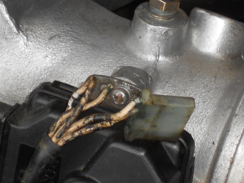
It was running good with just the top two and probably the fourth wire hooked up. Does anybody have an idea why someone would disconnect the #3 wire and fold it back? I have all the parts to build a new connector but will put it back together like this to make sure it still runs.
I have just a few more things to do to finish it up. Any ideas would be appreciated!
152630895.jpg
 
Not to hijack but if you ever have any spare d-jet parts like a pressure sensor, or an ecu let me know. just bought a 1972 144 and i need parts to get it running right. thanks
 
What year
what model
what fuel / ignition systems
what *mods* have you done??[/QouTE]

1972 142E gas with 123 distributor. The only mods I have done is the 123 distributor and have just installed a VV61 Isky cam and new stock lifters. It was running fine until the bottom of a lifter went concave and the cylinder was rapidly dying. I took it apart to have the head redone and install the new cam. I had several brittle wires so I bought some parts to replace the bad connectors and protective boots. I have a new plug for the throttle position switch and will install it with the top two wires in place and a new connector on the broken wire. Hopefully it will restart and run like before I took it apart. I guess my main question is why anyone would fold the third wire with the good connector back, and if a problem could have been solved by doing this.
 
do you have THIS:
http://www.volvowiringdiagrams.com/volvo/Vintage Info/140 Greenbook.pdf ???

and THIS:
http://www.volvowiringdiagrams.com/...5 164e 1800e Fuel Injection Fault Tracing.pdf

http://www.volvowiringdiagrams.com/volvo/Trouble Shooting Guides/Bosch Fuel Injection Systems EN.pdf

http://www.volvowiringdiagrams.com/...s/Volvo Problem Solver Advanced Edition-1.pdf

I *know* it's a lot of material but it's GOOD MATERIAL!!....when cars reach
the age of the one you're dealing with --- there have been MANY opportunities
for "bodge repairs"... make it run then test the systems for fault...(you can "retract"
the pins from the switch and then move them forward if need be...just tryin' to
streamline the process of getting it going again....
 
I went through something similar last winter. All 4 wires were popped out of the connector that goes to the throttle switch. Each of the white wires has a number code on it. They will be 17, 14, 20 and 9. My main issue was trying to find out the order of install into the connector.

The '72 Volvo Green book has a diagram on page 2-69. It shows the order from top to bottom as 9, 20, 14 and 17. I put them into the connector this way, but the car was still not running right.

I located the Volvo djet troubleshooting guide online, the one that shows the cartoon of the Vikings on the front. On page 2-31, it shows the orientation of the wires differently; 17, 14, 20 and 9, oriented top to bottom. When I hooked up the connector this way, my problem was solved.

I don't have the link to the troubleshooting guide at the moment, but can send it over tomorrow. I can also scan the specific page as I do have the printout showing the wiring orientation.

I didn't read over the links TrickMick had provided. This material may have been covered in there.

Good luck!
Hey Jack: It was covered here http://www.volvowiringdiagrams.com/v...0Edition-1.pdf at 23-551 and I read where the numbered order is sometimes reversed. Mine is wired 17,14,20 and 9 too I think. 17 and 14 are idle and CO and 20 and 9 are acceleration/ enrichment. Best guess is the acceleration one was disconnected, although the car ran good before the lifter went concave. Thanks and its good to hear from you!
 
Not to hijack but if you ever have any spare d-jet parts like a pressure sensor, or an ecu let me know. just bought a 1972 144 and i need parts to get it running right. thanks
No problem! These parts are getting harder to find. I do plan to sell the B-20 that is now in my car complete with transmission(M40) and all the Djet items with the possible exception of the intake and exhaust manifolds if I decide to go with fuel injection instead of duel Solex side drafts when I get my stroker motor together. Put a wanted ad here, ipd, and Brickboard and you will probably find what you need. Good Luck!
 
Got the wires clean enough to identify

The switch on my car has the numbers reversed from what the schematic says. My wires were going to the correct position on the switch with the exception of the #14 wire, which was disconnected and taped back. The #14/12 is for idle and CO. When I get it running again I attach the wires like they were til I get it running. Then I'll hook up the #14 wire and see what happens.
 
I located the Volvo djet troubleshooting guide online, the one that shows the cartoon of the Vikings on the front. On page 2-31, it shows the orientation of the wires differently; 17, 14, 20 and 9, oriented top to bottom. When I hooked up the connector this way, my problem was solved.

I don't have the link to the troubleshooting guide at the moment, but can send it over tomorrow. I can also scan the specific page as I do have the printout showing the wiring orientation.

http://volvo1800pictures.com/document/fuel_injection_fault_tracer/fuel_injection_fault_tracing.pdf
 
Back
Top