• Hello Guest, welcome to the initial stages of our new platform!
    You can find some additional information about where we are in the process of migrating the board and setting up our new software here

    Thank you for being a part of our community!

Unshrouding Exhaust Valves -- Pics?

cooltouch

New member
Joined
Dec 31, 2005
Location
Houston, TX
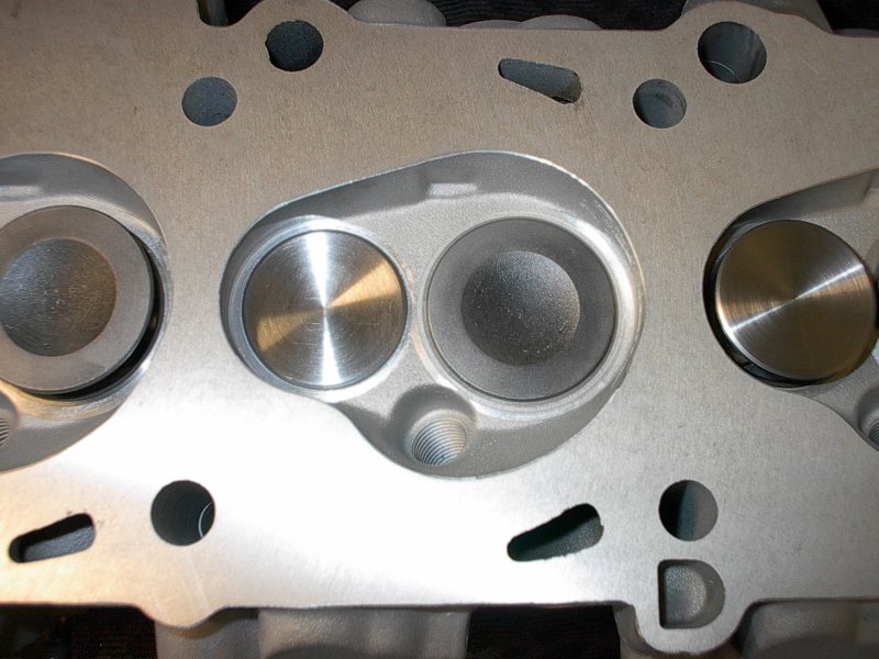
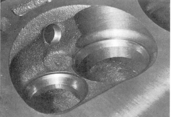
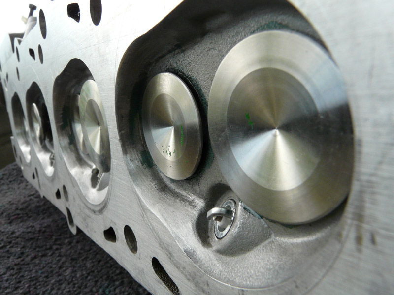
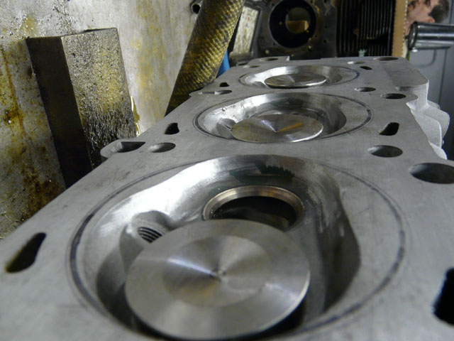
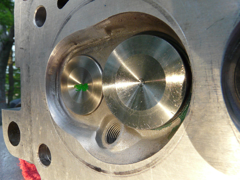
I plan to unshroud the exhaust valves on my B230FT 530 head. I've seen this done before on other heads, but I'm wondering if anyone here has done it, and if you might have any pics you could post of your work?

I bought some bits for my Foredom tool (like a Dremel with flex shaft on steroids if you don't know what it is) that are about 3/4" diameter by about 1/4" thick with rounded edges. These were the best bits I could find for what I think I'm gonna need for this job. Any input you might care to offer would be appreciated.

Best,
Michael
 
Last edited:
Here is a picture of what the machine shop did when I asked them to unshroud the valves. Those are standard intake valves and stainless 38mm exhaust valves.

75561903.jpg
 
Last edited:
Going to be a pain with a dremal kinda tool. If you are doing a valve job, just have your machinest do it. They have a tool that does it perfect in a few seconds.
 
This is not the kind of thing that you get out your dremel and just do. Some practice with a junk head would be a good step toward learning head work and doing it well.
 
Thanks for the pic Wennstroma.

I've PnP'd several heads before this one, mostly B230FT heads. I've even unshrouded the valves, in a similar fashion as the above machine shop has done. You know, where you scribe a circle matching the headgasket fire ring, and then remove material up to that edge.

After completing the PnP job on one head, I took it to a local performance machine shop for a valve job, and mentioned to one of the guys there that I'd PnP'd it. He was quite enthusiastic about the whole process, gave me a tour of their facility (including their flow bench), and when I showed him what I'd done to unshroud the valves, he showed me how they did it. I'd seen this same sort of cut made once before, but that was the only other time I'd seen it. Here's a pic that shows more or less what I'm talking about, borrowed from the corvette forum:

47644709d1257888456-converting-the-461-1-94-heads-into-2-02-heads-461chamber.jpg


This fellow told me that this was a better way to do it cuz you didn't have to worry about cutting too close to the edge of the gasket ring, and also it didn't affect the squish area. The way he'd done it on the head he showed me, though, he hadn't cut into the CC roof the way it was done in the above pic. Instead he'd cut into the CC wall more or less flush with the roof. It wasn't a very deep cut -- probably no more than 1/8" or so.

My reason for starting this thread was to find out if anyone else here unshrouds their valves in a similar fashion.

Best,
Michael
 
My machine shop told me they would definitely unshroud the valves on the 530 style head I brought him. At the time he was working on my 531 head and he said that was better than the 530 head with the valves already unshrouded. Give it a try if you are comfortable with the process. I was just trying to tell you to be cautious because I don't want you to ruin the head.

There are some good gains to be had from other work as well. You should look into that, too. There are already some good threads about headwork on here hopefully with the pictures still working in the them.
 
I dug around some on a back-up drive where I keep old images and stuff, and found a drawing I'd made shortly after talking to this guy at the performance machine shop, which indicated the way they unshroud valves. It shows things much clearer than I can describe with words. Obviously the dotted lines indicate where the cuts would be made and are somewhat exaggerated in terms of depth.

unshroud.jpg
 
Last edited:
I dug around some on a back-up drive where I keep old images and stuff, and found a drawing I'd made shortly after talking to this guy at the performance machine shop, which indicated the way they unshroud valves. It shows things much clearer than I can describe with words. Obviously the dotted lines indicate where the cuts would be made.

unshroud.jpg

I'd weld some more material on those areas. That cut will def slow/stop the flow.
 
i cut directly down back to the fire ring around 38mm exhaust valves and tapered it back in. left the shape of the rest of the chamber unchanged. mostly because i didnt want them to be uneven, i sued a template to keep them consistant. i did cc them after my work with the dremel and no adjustments were necessary. i cant say i have heard of the method you describe being done before.

DSC00407.jpg
 
I'd weld some more material on those areas. That cut will def slow/stop the flow.

That method is fairly common where deshrouding is restricted by the gasket ring diameter, the sketch is a little exaggerated for illustration. It isn't ideal, but where oversized valves are being used shrouding can otherwise be bad.


Where there is enough room for normal machining around the valve seat it is better to form a small radius at the base of the cut like in the second and later photos. The first photo looks to be a very square cut which is both worse for flow and could possibly introduce a stress raiser in the chamber where material is already being removed and reducing its thickness.
 
Thanks for the input, Turbeam. Good point about stress risers. That hadn't occurred to me.

I did some more digging and found an old photo of a combustion chamber on the first B230FT head I ported -- back in about 1998. Never had the head's flow measured, but lemme tell ya, that old 745T would sure scoot.

b230fthead1.jpg


I opened up the CCs to the edges of the gasket rings. Not much of a radius at the bottom. I did what I could to maintain as much of a slant as I could to the walls around the valves.

I think mine ended up looking a lot like Volvo240GLE's. Can't really tell about towerymt's -- all the photos are at oblique angles, but it looks similar at least.
 
The side of the chambers where the valve and gasket/ bore circumferences radiuses come closest is the biggest problem, particularly with large oversize valves, and there often isn't too much that can be done there. This is often much more of a problem on the average 2VPC engine.


At either side of that point where the two are getting further apart I would usually take more advantage of this and cut right out closer to the gasket ring and blend this back into the radius on the chamber side of the valve seat. This might sacrifice a little squish area (which could be regained elsewhere?) as well as increase the chamber volume, but flow on either side of the valves is so important I believe it takes priority.


The vast majority of my head work has been with N/A engines of various types, but it is my belief that on a typical turbo motor that improvements need to be biased more towards the exhaust side anyway......and it helps to remember and visualize exhaust flow trying to find its way to and past the valve in the opposite direction from the inlet side, which can make a big difference as to how to go about improving things.....
 
I don't really think a little increase in chamber volume is that big of a deal with a turbocharged engine. While one does lose a bit of CR, it also means more fuel/air that can be packed into that space. And I agree about biasing one's efforts toward the exhaust side. One needs to keep velocity as high as possible.

It's been so long ago when I took the above pic of the 745T's cc that I don't recall now if I had done an additional mod to the cc before or after I took that photo. It looks like I took the photo before I did it. I removed a fair amount of material from the curve in the cc's wall between the exhaust valves and the spark plug holes, straightening the "kink" out a bit. I was corresponding with a Swedish tuner back then, who recommended I do this. He called it a "Group B" cc mod. I also had the head decked 0.010" which probably largely made up for the material that was removed.

I'm not going to get into that level of grinding with this head, though. The car is a 1990 764T and other than a moderate increase in boost and the PnP of the head, that's all I really plan to do to this car's engine. If I ever get ahold of a 945T though, look out. :cool:
 
Using a Dremel type tool on an aluminum head is a good way to do it. If you use powerful equipment, like a die grinder, and make big fast cuts, you are more likely to make mistakes.

Use the photos that towerymt posted. Those are done the correct way.
 
Well, I just finished it. I decided not to go with the "undercut" method because the bits I bought for this procedure -- which were the only ones I could find that looked even close to what I'd need -- were too thick. So I just did the same as I have before, and as you guys did. Except I was a bit conservative. I opened up the CCs not quite to the edge of the gasket ring. I used a sharpie to locate the ring's position and cut just down to the sharpie line. So I left about 1mm or so from the edge of each cc to the gasket ring. Good enough for this application.

Actually, when using a steel bit on a Dremel-type tool, one can make rapid progress. I used my Foredom, which I like better because it has more torque and the handle is more massive and more stable in my hand. I have found the key to removing metal freehand is to do it with confidence. Sure, firm strokes across the entire length of the surface that material will be removed from will result in smooth even removal. Timidity leads to hesitation, which will cause divots. Short back-and-forth strokes also tend to result in an uneven surface.

I went back over the cut areas with a stone bit to smooth it out some because even when done right, the steel bit will leave a sort of pebbly texture. Then I went over everything again with Craytex bits to smooth it even more, and lastly sanded down the cc with 220-grit sandpaper. It's looking pretty good now. I took a few pics, which I'll post later.
 
46mm / 38mm cut into stock seats, 531 penta head
113755513.jpg


112337824.jpg


112981392.jpg

I'm bumping this dinosaur thread for it's great pics and have a ??? for Towery.
Whats the approx angle of your de-shrouding work shown on the pics around the exhaust valves?
It looks like it's tapered or radius'd, which I'd prefer over just boring straight down like shown in the other pic.
 
Sharp corners in a CC is usually not a good thing for flow and can cuase hot spots that can cause pre ignition IIRCC.
 
Back
Top