• Hello Guest, welcome to the initial stages of our new platform!
    You can find some additional information about where we are in the process of migrating the board and setting up our new software here

    Thank you for being a part of our community!

Megasquirt dead after extended wiring harness

Joined
Sep 9, 2007
Location
Hellas(Greece)
Hello,
long time no see...I had my 244t left for 7 years and before 5 days managed to resurrected it :-)
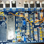
Today I tried to extend the wiring harness of my ms1 v3.0 distributor based.
I cut and extend each wire once at time,in order to avoid miss-connection but once I tried to start the engine,nothing happened...No led on,nor fuelpump runs
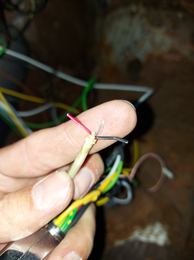
The only cable that was tricky,was one that contained a black, a red and a nude wire.Although even if I connect them wrong or miss connect one, those 3 wires are to thin to cause malfunction to ms
Any thoughts?
TocoBc.jpg
 
The shielded wire is for the crank position sensor and will not affect power up.

I'd check that something is not pulling down the 5vRef, The processor runs on 5v, if something is pulling down the 5v it will not wake up.
 
He mentioned it is a distributor based MS. So that shielded wire could be for the Hall sensor. No powerup may mean a bad fuse if you connected the power source to the fuse box. Check that the unit gets 12v to power up.
 
Where 12v enters the circuit board. There should be a voltage regulator IC that brings the voltage down to 5v for the microprocessor. Those can fail and you lose the power to the chip. Sorry I don't have a schematic and cannot tell you the component number on the board.
 
If Hall wiring is mixed or shorted it might mess the 5 volt regulator and there is no life on the board. Recently had troubleshoot a MS2 V3 because of this.

So measure that you have both 5 and 12V on the board.
 
post a picture of the board.
L8hSom.jpg

hKQjsa.jpg


If Hall wiring is mixed or shorted it might mess the 5 volt regulator and there is no life on the board. Recently had troubleshoot a MS2 V3 because of this.

So measure that you have both 5 and 12V on the board.

In order to extend this wire,I striped the black and red wires and add 1.5m extention as well as the nude wire.
 
The large transistors on the heat sink are what you are looking for. There should be ones marked with 7805 and 7812. They are the voltage regulators for the board. The other large transistors will be injector drivers.
 
Do you have a diagram showing how your MS setup was wired?

Normally, there's a main relay that is energized by the ignition switch. The main relay provides power to the MS. Once the MS has power, the LEDs should light up, unless the LED circuitry has been modified from the standard configuration.

I'd unplug the MS and check that it's getting power from the main relay when the ignition switch is turned on. You can use a bent paperclip to probe the connector. The paperclip should fit the contact loosely. If not, find a smaller wire to prevent damaging the connector.

Main power to MS is pin 28, and ground pins are 1,2,7 thru 19.

The MS includes a couple polyfuses. These fuses will open when the MS circuits, or the external circuits on +5volts Vref, draw too much power. They'll close once power is turned off and they cool down. It may still be possible to damage some circuits if wiring is not correct.
 
Back
Top