• Hello Guest, welcome to the initial stages of our new platform!
    You can find some additional information about where we are in the process of migrating the board and setting up our new software here

    Thank you for being a part of our community!

I'm about to Modify this MS 2.2 box and want a *thumbs up*

MrBill

fige=500Dollar Mistake
300+ Club
Joined
Jan 1, 2006
Location
Southern Maryland
It's MikeP's brown244 - Morley.
MS box is a Kenny Howard assembled unit. 2.2 board, ms1 chip
LH 2.2 block mount distributor.
Some sort of external ignitor. Probably BIP373, but I have a spare 960 ignitor. Not sure If I can just use one channel of the 3-channels, but that would be sweet.

From DIY's article:

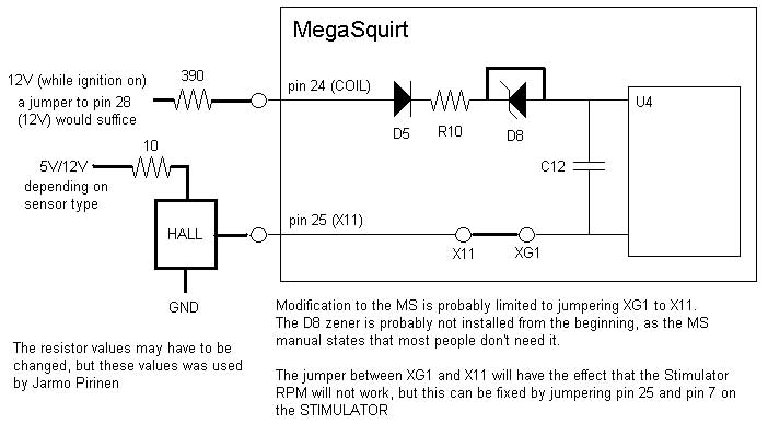
MegaSquirt-I PCBv2.2 Mods Required:

Remove D5, D8, and R10. Also remove the jumper between XG1 and XG2.
Replace D8 with a 1K resistor. this is currently jumpered
Run a length of wire from XG1 to the right hole of D5.
Run a wire from the bottom hole of R10 to the top of R11.
Run a 750 ohm to 1K, 1/4 watt resistor from the right (5v) side of R23 to the negative (top) leg of D17.
Run a wire from the negative leg of D17 to X11.
That's it!


Thoughts?
 
lemme throw this down and see if the box is setup thusly:
28423889.jpg


spark out will be the Fidle, there may be an old ignition transistor in there, but it will almost certainly not be a bip, it'll probably be a vb921 if that's in fact what it is. it may also be a tip122 for the idle valve, but that would have been something someone specifically requested. post a pic of the board.
 
lol. nah it's good. looks like for some reason xg1-xg2 is jumped, if the wire is soldered, it was something that was requested at the time. do the xg1-x11 and follow the diagram I posted earlier, should be good to go with the spark output coming out the fidle (unless you want to move it to one of the LEDs).
 
mikeP had his students do work to the car moons ago, they may have done the modification.

So the fidle pin (30)is now going to go to some external ignitor I need to set up.

The diagram you've posted is pin 25 being the hall sensor's input, and pin 24 becoming the pullup resistor?
 
mikeP had his students do work to the car moons ago, they may have done the modification.

So the fidle pin (30)is now going to go to some external ignitor I need to set up.

The diagram you've posted is pin 25 being the hall sensor's input, and pin 24 becoming the pullup resistor?

yep
 
Okay so the car is all done. It doesn't run, so that's cool. The FP wiring is fubar I think - I've got 12 at the pump connector but not the pump.

Either way... I tried to get it going with some brake cleaner. I have questions.

The distributor seems correctly seated. At TDC, the rotor is right above #1 plug. What ballpark trigger offset should I have?

With the BIP373 being triggered, am I inverted or no?
 
On my car I just got running with the LH2.2 dist, it took a trigger angle of 42* to get my timing in line. It would run with it at 60*, but wasn't happy and it wouldn't idle. When I dumped it to 50*, the car would idle on it's own so I could get the timing light on it to get it all kosher.
( I should mention that I came across this info on here after digging through a few threads. Basically, it was said to find what works and use it for the Trigger Angle)

Using the BIP373's you should have spark inverted.
DIY Write-up
 
Last edited:
yeah so we were in the ballpark enough that we should've had it pop and stuff at least.

New fuel pump to replace the brand new fuel pump just came in, so if it's not too cold I'll try and get it in tonight and try more.
 
Back
Top