
the poi
Has been
- Joined
- Jan 5, 2003
- Location
- Pasadena, CA
Alright, boost + a/f meter in your dash. For those who are anti-NB a/f meter, you can use this design with a WB with a NB output or make a realtively simple change in the wiring to use the 5-0v output
To start, the pbase page with a lot of pics of it, 'fraid I didn't get too many in the process of building it, didn't have a digicam at the time
http://www.pbase.com/765ti/airfuel_guage_and_boost_gauge
The boost gauge is a VDO, I THINK its a Vision, its backlit with an incadescent bulb. You can see here
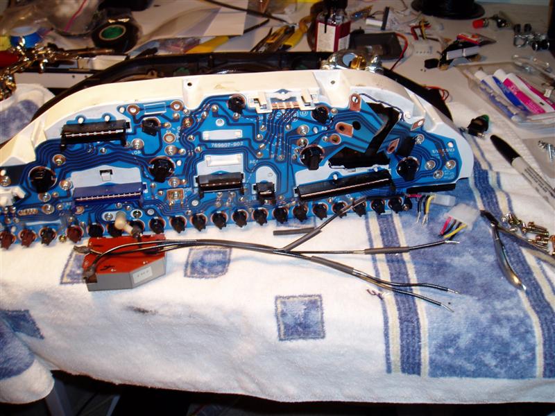
how the area behind the clock has been cut out form the instrument cluster back, and the plastic "circuit-board" has been cut. The traces that were cut through, I scraped off the installation and soldered on some wires to bridge the gap and leave enough room to get the gauge in. You also have to relocate the dimmer control module as well if you have to cut through the plastic back of the instrument housing.
Point is, if you can find a "shallow" boost gauge that lets you get by with just drilling a hole for the wires to the A/F meter and a hose to the boost gauge, use that instead; it'll probably save a lot of time.
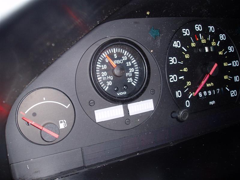
As for the A/F meter: I have two LED bar graphs (I have mine setup with the one on the left calibrated from 0-1v and the one on the right from .7-1v, for extra WOT resolution) that are mounted flush with the gauge face. The ground "lead" from each LED is soldered to a wire on a ribbon cable, a + lead connects to all the positive leads, its all bundled up, and the bundle goes to the control unit.
LED's on panel:
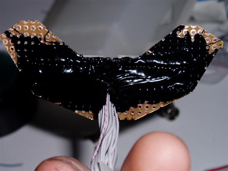
(the black stuff is an insulating compound that is opaque. You need something like this to block out the light coming from the big incadescent bulbs in the cluster, as the LED bar graphs are somewhat transluscent and will glow kinda yellowish if lit from behind)
Connector and control unit:
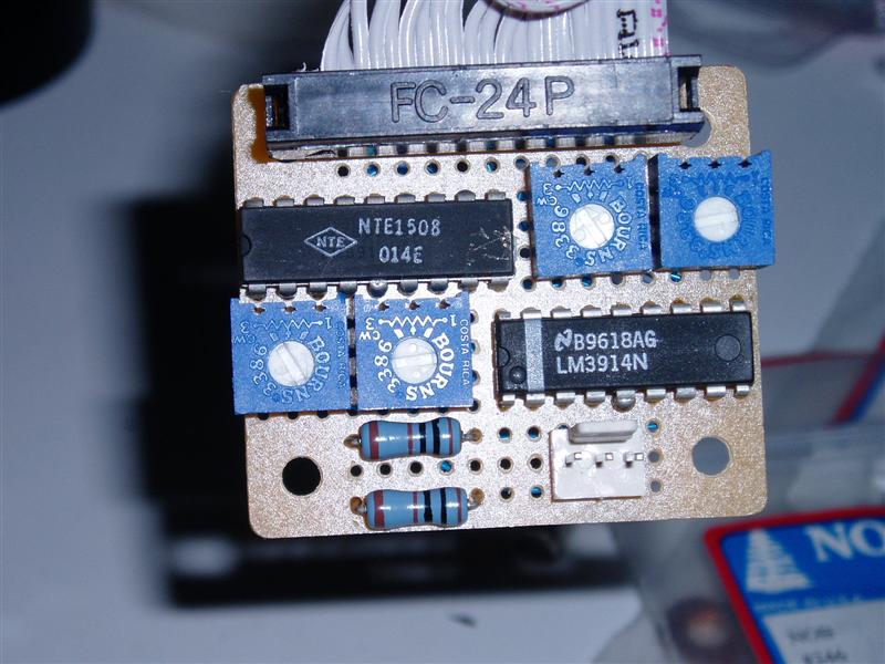
The control unit is the fun part. By mounting the controller far from the gauge, you can pretty much solder components onto any size proto-board, but I went for as small as I could (my controller is in a small project box and is taped to the back of the instrument panel, theres very little room back there tho, so you may need a long piece of ribbon cable if you go with a bigger board mounted farther from the dash)
The wiring can be a little nasty on a small board ( http://www.pbase.com/image/20638031 ) but it can be done.
Overview of the components:
The connector on the bottom right takes in 12v, ground, and the O2 sensor signal. Theres essentially two controllers on the board, one for one gauge and one for the other. Theres a chip, two pots, and a resistor for each LED set; the chips are the main drivers, and the pots are how you set the lower and upper bounds for each LED set.
The wiring!
This is a diagram for the BACKSIDE of the proto-board I used, so everything will be flipped compared to looking at the components:
Wiring it up is pretty much a matter of matching name to name. If theres more than three pins with the same name, jsut wire them all together, it doesnt matter what order, just as long as they're all connected. the RefA's are just names for the pins on the chips, they just get grounded (hence the blue -)
Also apply the wiring here to the conenctor to the LED's. Note how one + line powers all the LED's, they just get grounded (and thus lit) by the chips according to the numbering.
The components, whered to get em:
Controllers: Two NTE1508's, or LM3914's, might be some other ones that do the same thing. Here's the datasheet for the 1508: http://www.nteinc.com/specs/1500to1599/NTE1508.html
You can get these from www.digikey.com or www.mouser.com
Potentiometers(Pots): Two 10k ohm. Anyhting board-mount will work, small for something the size of proto-board I used.
Resistors: You need two, these control coltage to the LEDs. Im not sure what I'm using, safe value are maybe 470-1k. Higher resistance, dimmer lighting. Ill have to check and see what Im using
Connectors: Any three-pin that you can solder to a board, might need to use soemthign else. Also need something for the LED's, ribbon cable connectors work well. Can probably get this stuff at Fry's, other electronics stores. Might need to call around, as the size I used is pretty rare
Setting the pots:
Looking at the gauge to see which pots control which input, theres a low and high for each LED. Setting is pretty easy (althoguh you'll need a voltmeter/multimeter)
Check the voltage between (1/2)D(Lo/High) and ground. You can adjust from 0 and 1.25v. I, for example, have 1DLo=0.00 1DHi=1.00 2DLo=.70 2DHi=1.00 . I've been debating what to set the highs at: I've heard a lot of people saying .9 is more or less the max a narrowband will put out when pretty rich, although one guy (thelostartof) with huge injectors is running pig-rich at high RPMs and is seeing .95 or so peaks. You can always pull the panel and change these later (if you have the control unit mounted far away, like jsut under the kickpanel, you can probably change it right in the car, may be a reason to mount it pretty remotely)
The gauge panel:
This is probably the hardest part. I used some thick gauge sheet metal from Home Depot. I'd go with the thickest you can work with. Once you crack off the backside of the instrument panel, you'll have an idea of the shape you're trying to get for the outside. You want to use the two "ears" and the two flat side for stability and alignment. Once you get the outer shape cut, I used a dremel and made rough cuts with a "spinning sawblade"-type attachment (pic from my pstroke install...holy hell I'm low-budget http://www.pbase.com/image/24986532.jpg , then made final sanding with a grinding wheel, you can start on the LED and boost gauge cutouts. When setting up your cuts for the boost gauge, if theres a "flashing" or lip on your boost gauge, make sure this will clear the instrument panel, "lip." If you want it to sit flush, the distance form the top of the panel and the top of the gauge cutout will the the lip of the instrument panel and the flashing on the boost gauge. This will be a lot clearer looking at it...
File out the sharp corners of the LED faces with a file, and you're set.
This is a diagram of my cutouts, the line in the bottom left is one inch.
http://www.pbase.com/image/20643665
Copying this, then printing it, and re-tracing it however may introduce a lot of error, so you may be better off tracing how you're going to cut the guage mounting metal yourself.
You can see some of the pics on my pbase account showing roughly how the screws are holding the LED's flush with the face. Heres a good one:
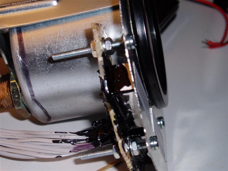
Again, all that black stuff keeps light from the big incadescents from blasting through the gauges and making it "glow"
Again, returning to the boost gauge mounting, and really, the whole thing in general. The 88/90+ panel gives you VERY little room behind it, so be as prudent as possible with mounting/moving components. My VDO Vision, for example, couldnt clear a brace from the back with a vacuum hose attached. I ended up using heatshrink and epoxy to make a really thin hose that could clear the brace and connect to the vac line. If my boost gauge was a millimeter more the the right, I would've had to trim off some of teh brass barb. May want to look into a different gauge, but the text and the green light on the VDO does match the interior quite well.
This thread is like one of those cooking shows, they TOTALLY don't show you enough to actually make yourself whatever they're making.
<ahem>
stir for five minutes and VOILA:


____________________________________________________
This was somewhat of a clip from some PM's, if anyone has some time to blow (or is planning on this) post stuff that the description gets hard to understand... I'll draw some fancy MSPaint diagrams for em. I'm also gonna try to get a material list in here somewhere...
To start, the pbase page with a lot of pics of it, 'fraid I didn't get too many in the process of building it, didn't have a digicam at the time
http://www.pbase.com/765ti/airfuel_guage_and_boost_gauge
The boost gauge is a VDO, I THINK its a Vision, its backlit with an incadescent bulb. You can see here
how the area behind the clock has been cut out form the instrument cluster back, and the plastic "circuit-board" has been cut. The traces that were cut through, I scraped off the installation and soldered on some wires to bridge the gap and leave enough room to get the gauge in. You also have to relocate the dimmer control module as well if you have to cut through the plastic back of the instrument housing.
Point is, if you can find a "shallow" boost gauge that lets you get by with just drilling a hole for the wires to the A/F meter and a hose to the boost gauge, use that instead; it'll probably save a lot of time.
As for the A/F meter: I have two LED bar graphs (I have mine setup with the one on the left calibrated from 0-1v and the one on the right from .7-1v, for extra WOT resolution) that are mounted flush with the gauge face. The ground "lead" from each LED is soldered to a wire on a ribbon cable, a + lead connects to all the positive leads, its all bundled up, and the bundle goes to the control unit.
LED's on panel:
(the black stuff is an insulating compound that is opaque. You need something like this to block out the light coming from the big incadescent bulbs in the cluster, as the LED bar graphs are somewhat transluscent and will glow kinda yellowish if lit from behind)
Connector and control unit:
The control unit is the fun part. By mounting the controller far from the gauge, you can pretty much solder components onto any size proto-board, but I went for as small as I could (my controller is in a small project box and is taped to the back of the instrument panel, theres very little room back there tho, so you may need a long piece of ribbon cable if you go with a bigger board mounted farther from the dash)
The wiring can be a little nasty on a small board ( http://www.pbase.com/image/20638031 ) but it can be done.
Overview of the components:
The connector on the bottom right takes in 12v, ground, and the O2 sensor signal. Theres essentially two controllers on the board, one for one gauge and one for the other. Theres a chip, two pots, and a resistor for each LED set; the chips are the main drivers, and the pots are how you set the lower and upper bounds for each LED set.
The wiring!
This is a diagram for the BACKSIDE of the proto-board I used, so everything will be flipped compared to looking at the components:
Wiring it up is pretty much a matter of matching name to name. If theres more than three pins with the same name, jsut wire them all together, it doesnt matter what order, just as long as they're all connected. the RefA's are just names for the pins on the chips, they just get grounded (hence the blue -)
Also apply the wiring here to the conenctor to the LED's. Note how one + line powers all the LED's, they just get grounded (and thus lit) by the chips according to the numbering.
The components, whered to get em:
Controllers: Two NTE1508's, or LM3914's, might be some other ones that do the same thing. Here's the datasheet for the 1508: http://www.nteinc.com/specs/1500to1599/NTE1508.html
You can get these from www.digikey.com or www.mouser.com
Potentiometers(Pots): Two 10k ohm. Anyhting board-mount will work, small for something the size of proto-board I used.
Resistors: You need two, these control coltage to the LEDs. Im not sure what I'm using, safe value are maybe 470-1k. Higher resistance, dimmer lighting. Ill have to check and see what Im using
Connectors: Any three-pin that you can solder to a board, might need to use soemthign else. Also need something for the LED's, ribbon cable connectors work well. Can probably get this stuff at Fry's, other electronics stores. Might need to call around, as the size I used is pretty rare
Setting the pots:
Looking at the gauge to see which pots control which input, theres a low and high for each LED. Setting is pretty easy (althoguh you'll need a voltmeter/multimeter)
Check the voltage between (1/2)D(Lo/High) and ground. You can adjust from 0 and 1.25v. I, for example, have 1DLo=0.00 1DHi=1.00 2DLo=.70 2DHi=1.00 . I've been debating what to set the highs at: I've heard a lot of people saying .9 is more or less the max a narrowband will put out when pretty rich, although one guy (thelostartof) with huge injectors is running pig-rich at high RPMs and is seeing .95 or so peaks. You can always pull the panel and change these later (if you have the control unit mounted far away, like jsut under the kickpanel, you can probably change it right in the car, may be a reason to mount it pretty remotely)
The gauge panel:
This is probably the hardest part. I used some thick gauge sheet metal from Home Depot. I'd go with the thickest you can work with. Once you crack off the backside of the instrument panel, you'll have an idea of the shape you're trying to get for the outside. You want to use the two "ears" and the two flat side for stability and alignment. Once you get the outer shape cut, I used a dremel and made rough cuts with a "spinning sawblade"-type attachment (pic from my pstroke install...holy hell I'm low-budget http://www.pbase.com/image/24986532.jpg , then made final sanding with a grinding wheel, you can start on the LED and boost gauge cutouts. When setting up your cuts for the boost gauge, if theres a "flashing" or lip on your boost gauge, make sure this will clear the instrument panel, "lip." If you want it to sit flush, the distance form the top of the panel and the top of the gauge cutout will the the lip of the instrument panel and the flashing on the boost gauge. This will be a lot clearer looking at it...
File out the sharp corners of the LED faces with a file, and you're set.
This is a diagram of my cutouts, the line in the bottom left is one inch.
http://www.pbase.com/image/20643665
Copying this, then printing it, and re-tracing it however may introduce a lot of error, so you may be better off tracing how you're going to cut the guage mounting metal yourself.
You can see some of the pics on my pbase account showing roughly how the screws are holding the LED's flush with the face. Heres a good one:
Again, all that black stuff keeps light from the big incadescents from blasting through the gauges and making it "glow"
Again, returning to the boost gauge mounting, and really, the whole thing in general. The 88/90+ panel gives you VERY little room behind it, so be as prudent as possible with mounting/moving components. My VDO Vision, for example, couldnt clear a brace from the back with a vacuum hose attached. I ended up using heatshrink and epoxy to make a really thin hose that could clear the brace and connect to the vac line. If my boost gauge was a millimeter more the the right, I would've had to trim off some of teh brass barb. May want to look into a different gauge, but the text and the green light on the VDO does match the interior quite well.
This thread is like one of those cooking shows, they TOTALLY don't show you enough to actually make yourself whatever they're making.
<ahem>
stir for five minutes and VOILA:
____________________________________________________
This was somewhat of a clip from some PM's, if anyone has some time to blow (or is planning on this) post stuff that the description gets hard to understand... I'll draw some fancy MSPaint diagrams for em. I'm also gonna try to get a material list in here somewhere...

")