• Hello Guest, welcome to the initial stages of our new platform!
    You can find some additional information about where we are in the process of migrating the board and setting up our new software here

    Thank you for being a part of our community!

Arduino LH Jetronic interface: live data + MicroSD logging + ELM327

apollokid

Member
Joined
Aug 10, 2020
Location
Milan (Italy)
Hello everyone, my name is Diego and I live in the north of Italy. I recently posted a question in this forum about the reverse engineering of the Tq-signal that the LH Jetronic send to the EZK.
I've immediatly found some users interested when I described the project on which I'm working on and I was invited to open a new topic to create a place where to talk about and to share tech information and experiences.

Since it's impossibile to query the live data from the LH-Jetronic of my Volvo 945 I decided that I could try to build an interface that, acting like a network sniffer, decodes all the I/O signals directly through the control unit connector using my DIY breakout-box.

This is a picture of the board in the state it is today:
ACtC-3fPo3tOiMirIuh6tlgPi8X6UTnlCSzbrOavivQf7fBn5uJXTHUdlTxVTrwiDYedlRRKiBUU1DtuE206VxRDBCtfJ5nHi2fYNVMiNr81IcDUkiu_L90xqU-hYNpyUTn96njYY4CzAiNMdKbcwfaINYyx=w1024-h768-no


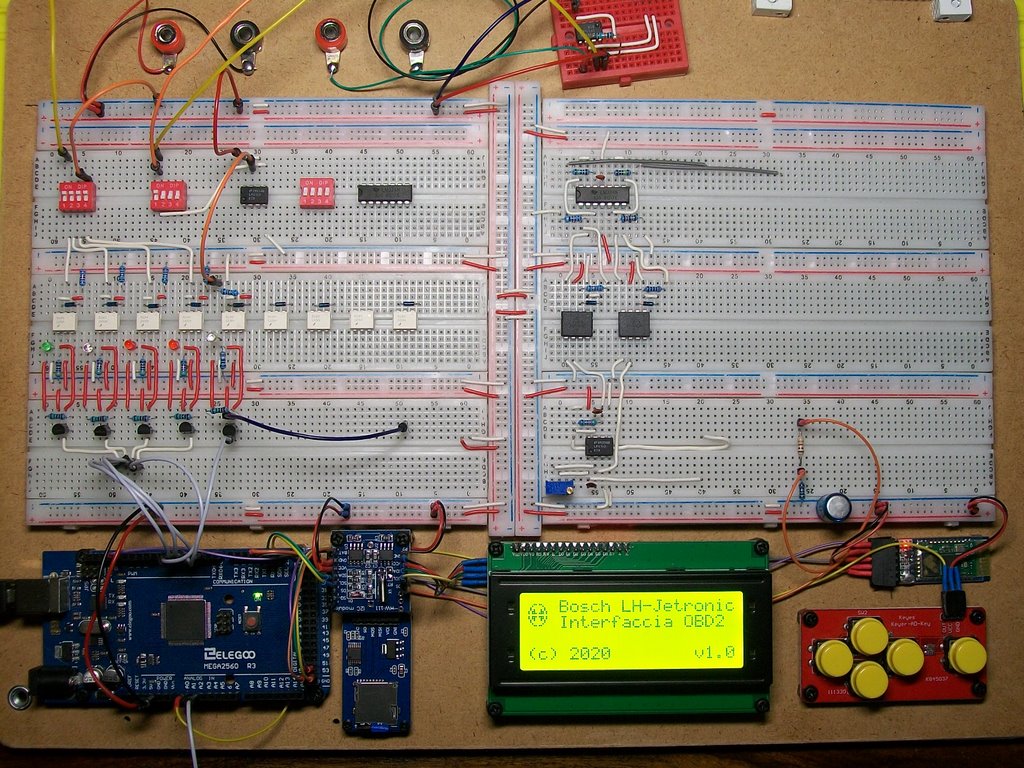
The project started last summer when I decided that it was the time to learn something about this Arduino who talk everyone. Today it's still under development and some parts are yet missing but the board is already usable for some tests and it is in a state that is much more than a proof of concept.

The board is divided in 3 main layers:
  • 12V car layer: here I put all the circuitry that is powered by the battery of the car. Here is where I put active filters, resistos, OpAmps and anything I need to drive the led of the optoisolators. I've also used some microswitches to be able to enable/disable each single signal without disconnect any wire.
    I still have to add an overcurrent protection circuit (a couple of fuses it could be the minimum)
  • Optoisolators layer: here I put the optoisolators (now I'm using both the 4N35 for the digital signals and the HCNR201 for the analog ones)
  • Arduino layer: here I put all the 5V circuitry from the transistors of the optoisolators to the input pins of the Arduino board

The Arduino board I used is an Arduino Mega 2560 since it supports 6 interupt pins and many digital and analog input pins plus the following shields:

Here some screenshots of the GUI I've designed with a brief description of the available functions:


Injection screen

ACtC-3fEysEYsDe3I-0D13NB4NiKU5B5Rj2YobdMQ4Gnl3v2-GSZ0zAQ0HOEpS-A096-fRb-VhjvrU3vqT_4ESLWhQ3VbP4K4vUjY2Ym6ZQHmsmoswHnRm-9tNEqwPXY7NaFcwxAH-8035xKZamaqqkrchk2=w640-h263-no


  • Ton is the pulse time of injectors
  • Tq is the engine load (yet under reverse engineering, at the moment I read the raw pulse width in μs)
  • rpm is obvious
  • λ is a graphical tool that shows the deviation from λ=1 (stechiometric mixture), it uses a configurable lenght circular buffer to calculate a mobile avarage plus the voltage produced by the oxigen sensor
  • hummer is when engine is knocking (yet under reverse engineering)
  • switch is the idle switch on the throttle body
  • IAC is the PWM of the idle air valve that measures the opening %
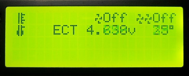

Cooling system

ACtC-3ezQou9XUln0L2BLn0Kghg1AZatji5PQ7Xn9h6wW-O8EAUGzUnp9vaah2aeEI9EzvMfjqNOn3fXRrsBZXrbTpbyHGUDJXWWGY10o9x99hdtHrC2ayJwLHmUD8tKKZUGusTppFG-mxSESkQmRbcgIj2h=w640-h259-no


  • 1 Fan: show when radiator fan is active at low speed
  • 2 Fans: the same at high speed
  • ECT voltage: voltage of the ECT sensor but I support the LH doesn't read a voltage but a current that I could measure using a breakout-box
  • ECT temperature (at the moment I use a quadratic interpolation function base on the voltage but I don't think that is too much precise)


Oxigen sensor

ACtC-3c08IaHzYw6fhd7H6oDsfWnHh0a3dFMr4JD5HVwpIO9jwhDCDVkQUIPDX3t0T4XMEhPDNfTF_74wvkYfuGPllqq_RCF0tYwYwb9-GqdkfeKFzuoP9_c7-JHjvOxhnTaGkVkbZetzufHrXP1HyyJUhm1=w640-h256-no


  • Media mob. (in english mobile avarage): is the configurable lenght in seconds of the samples
  • n. camp. (in english number of samples): report how many samples are in the circular buffer
  • The λ % indicator reports for how much time the mixtures was rich or lean
  • Oxigen sensor voltage
  • Same λ graphical tool of "Injection screen"


Tachimeter

ACtC-3ccCuPGvdf9PJZ0H6XNdW3xwHnqot-_-3rrpNstogLOIUM8mQOCqqXpeOCw_G_pfdF7kcNvvl5vcut7XWkCHn3T14L9nmD8uRo9fTGQpSjBGREw6H2ftM8RLzzfRNaBgUZCyXPOgdSfm4oUOOt135dr=w640-h242-no


  • Giri (engine rpm)
  • Velocit? (vehicle speed)
  • Nice To Have: instant fuel consumption, must be measured the opening and closing latency of the injectors with a scope or by consulting a tech paper (more documentation is need)


ELM327 Emulator

ACtC-3e8VtXLVyLwCQ09hjWGZA85KLepWwlps4HBLqdf3etr4FQsB4-4Kg9kG6OkMkrmAdo7B3Tc9laBaTNBhuTieJa68o3DnwJ54zhQhMF3oNdzhatLNkcSRtxsQwst_GUxRKzkOkEl69sWYag6Jt6UUsoc=w640-h255-no


Report the status of the bluetooth ELM 327 emulator.
At the moment I support only the following PIDs but I want to supports as many as I can.
  • 010C engine rpm
  • 0105 Engine coolant temperature
  • 0114 Oxygen Sensor 1
  • 0D Vehicle speed (incomplete)

For this feature I made a derivated work from the library GTTurboEcu since the orginal version works only with SoftwareSerial and I had found some random hangs when the rpm signal that I was reading using interrupts changed quickly.
So I added the support to HardwareSerial too by introducing an abstract layer interface and in this way I solved all my problems.
NOTE: I've tested it only with Torque on Android but it may also work with other compatible scanners


MicroSD real time data logger

ACtC-3cdn-PZ-rfX2Kdkr7OBVHZBOch4ul6Q6liOEUuS4xGTmYS5oc0763LXYydcKAM9B5UslVEj6E9-WqBdv40ss8sW0JJEQVDPROoPN8MU040-yZPcz_Nt_KL4BBipbw1TGrIOGgetbftPGF7BqQco8tiE=w640-h244-no


To be implemented.
I've some ideas to be developed, for example I could create the commands to start/stop the logging and to choose which signal include or the max leght of each recording.
I was also think at a injection map reverse decoder (by only driving the car it could be relative easy to rebuild the real injection map also without accessing to the memory of the control unit and it could also be possibile to measure the deviation (min vs max) of injectors pulse width that could help in diagnosys (for example in the case of a roughly engine)
Any suggestion here in usefull features is really appreciated.


Setup

ACtC-3dNe7VWvUXK38zGxVIJdiAuAExnjjvF9mLvctD-IksgN6kK-5_UL-Ve7EFFU0wL9e2_lwTvUQb5CSMgktiJA9YbWpIjSYkUWOM4pFjLJhbeSKqZ7q5kG_U9sLnZfIgjJeGb6-sSDHT-CzHTR9bCyg1X=w640-h276-no


To be implemented
For example I would like to add i18n support


That's all
I hope to finish the board within this year but I don't have none that runs me back so I will take all the time I need.
Anyway I'm curious to start testing it on the car (at the moment I tested it only on my desk using a signal generator and a DIY injectors emulator that I build using a fuel relay drived by a Darlington transistor with a zener 60V diode as overvoltage protection to replicate as much as possible the same waveform of the real injectors)
Finally I will return to work on the software Kikad becasue It could be fantastic to get a PCB and collapse this large prototype board into a little device that stays in the palm of one hand.


Opss... I was forgetting to share you at least one picture of my DIY breakout boxes.
Without them and the my friend Picoscope 2204A this project could be really hard to carry on, if not impossibile.
Here more pictures hoping they could be useful to someone: https://photos.google.com/share/AF1...?key=SVBXQlJNSlBiNkV1TU5CSWZ5R2lMZVRiMExMek9R

ACtC-3dsCKjYT1ZsGNe7Y-m56mF6sAELSrcKGpihTYyDgZ6Lr6kIdeQXHwGc0p1VURKBGB0ul2feHZQmuRNiB5nIKv574tDsAi7NqqxSL3z-2kM71ovFp_3YTuGFO0sy_IHB_yYADA_qwRAP0WifTGJ07K2D=w1102-h826-no
 
Hi Diego, Wow, you've done a lot of work! Very nice.

A couple years ago, I started to work on a similar project to monitor LH2.4+EZK using a simple Arduino board. I wanted
- a dashboard Multi-Gauge LCD display for use while driving, and
- full speed logging for offline tuning and graphing

At the time, I was only monitoring the EZK signals, plus a Wideband O2 input and a MAP pressure sensor input. This is what my benchtop setup looks like, with a couple different displays (click pictures for bigger size).


The items shown are:
- RPM
- Load - the width of the ECU Tq Load signal in microseconds (proportional to injector on time)
- Vbat - battery voltage
- Idle - the TPS idle switch
- DegF - the coolant temperature, currently the raw ADC value, not yet converted to degrees
- AFR - Wideband O2
- Spk - spark advance in degrees
- Dwel - spark dwell time in milliseconds
- KpA - input from MAP pressure sensor (currently connected to pot for testing)

For testing, I have a LH2.4 ECU and a EZ116K connected with a chopped off harness to a simple engine simulator board. The switches are for some of the sensors (temperature selects 3 resistors -- normal, hot, cold), and the one knob is for the MAF (or AMM) voltage. RPM (60-2 wheel signal) is from my Hantek oscilloscope pattern generator.


To connect to the EZK signals, I soldered wires to the connector pins inside the box. I think this will work in the car, but it's not pretty.


After working on the project for a while, I ran into some problems:
- The Arduino Nano that I was using didn't have enough pins to monitor EZK+ECU and support a LCD display
- Updating the LCD display (over SPI) was much slower than I liked.
- The LCD library (Adafruit GFX) occasionally glitched when sharing the Arduino with my interrupt-based measurement code. I think this is a common problem for Arduino libraries, that they don't work well with other interrupt based libraries.

I got busy with other projects and this one has been gathering dust for at least a year. With your inspiration, I've started to work on the project again.

Instead of using a single Arduino to do everything, I want to change the architecture to use 2 Arduinos. One would do all the measurements and only use a simple serial port interface. This can be connected to a Bluetooth module for logging and display on a PC or smartphone. If I can figure out the protocol, and there are not any legal issues, it would be nice to support TunerStudio or MSdroid software applications. For the in car dashboard multi-gauge, a 2nd Arduino and a small LCD display would be used, with a serial interface to the 1st Arduino.


I need to work through the available pins on an Arduino Pro Micro (32U4) to see if they can monitor all the ECU, EZK, and extra signals that I want. I'll post a pin usage proposal when I'm done.

In Italy, what hobbyist PCB companies do you have access to? There are a couple Chinese companies that are now offering PCBs plus assembly with common surface mount parts. Can you get PCBs from jlcpcb.com or seeedstudio.com?

-Bob
 
Very impressive, both of you. Definitely farther than I have gotten, mine is really only CLI software running on a laptop. I am especially jealous of those neat bread/perf boards. Mine always turn into jumbled messes.

I need to make me one of these bench setups to run LH and EZK out-of-car. My volvo is my second office!

It is news to me that the 'TQ' signal is proportional to injector open time. That is good to know.

For the OLED/LCD UI in the past I have used u8g2. I think it only supports mono screens but it is very lean and configurable. It leaves plenty of CPU time and memory for other things. I do like the idea of dual MCU boards with one being the data sampler and the other being the displayer/logger. Lots of room to grow

I am not a laywer but I think one can get around the fcc/radiation legal issues by just not including the bluetooth by default. Just let the end user source the bluetooth module separately and plug it in.:cool:
 
Last edited:
For the moment I didn't find flickering problems with the display but I'm using only 2 interrupt pins to read rpm, injectors pulse and Tq but may be I will need a third interrupt so I will have to find a solution.
My idea was to connect each digital signal to its own digital pin on the Arduino board and connect also each of these signal to an OR logic gate which output activates the interrupt pin.
The interrupt routine then should read all the digital pins of a port and then check each single bit in order, from the one with the hightest priority to the lowest.
It should not be a complex circuit in my opinion, and if the logic gate is sufficiently fast I believe that it should works.

For PBCs, I made only one little PCB in my life and for producing it I've used the jlcpcb.com service.
No SMD, only through hole components. Price and quality are very good in my opinion.
 
To chip in on the DIY PCB making, I've made several and prints through jlcpcb. SMD soldering is doable at home, just make sure you get thin solder, tweezers and a smaller soldering iron tip. I got a Velleman VTSS230, those also come with a hot air side so you can quickly reflow components to pull them into the pad nicely:)
 
Glad to hear that you can use jlcpcb.com. That makes it easier for anyone to order boards directly, instead of my needing to figure out customs and international shipping.

I was going to use KiCad, but I think we should try the online EasyEDA.com tools instead. I just setup an account at oshwlab.com so we can share design files. I've never used either of these before, so I hope they work well and have a high quality library of PCB footprints. It will be a learning experience.

My eyesight and nerves make surface mount assembly and rework challenging, but jlcpcb can do small volume SMT assembly with common parts. Are you OK with surface mount resistors/capacitors/diodes on the initial prototype boards? Probably 0805 and SOT-23 sizes (but I'll use bigger if jlcpcb has them in their common parts library). Or would you prefer all through hole so that you can assemble/modify it yourself?
-----
I'm still looking at the pin assignments for the Arduino. I'd like to monitor these signals:
- EZK: Vbattery, RPM, ignition, load, temperature, idle switch, knock enrichment
- ECU: MAF, injection, VSS (vehicle speed), IAC (idle air - optional?)
- Other: wideband 02, MAP pressure

Anything else I should try to include?
 
How are you measuring the car speed? I am currently doing a similar project but it is only for measuring the speed of the car, and not inputs from LH / EZK.

The technique I used was:

- Take sine wave signal from rear axle

- Filter through a full bridge rectifier to make it all positive voltage

- Use capacitors to smooth the pulsating signal into a smooth voltage level

- Use analogread() to measure this average voltage, which correlates to vehicle speed

Does LH have a different way of measuring vehicle speed?

Interested to know!

if I recall, the VSS sensor in the diff produces an AC voltage that is wired to the cluster speedo/odo. Inside that there is a UAF2115 chip which converts the AC frequency to a open collector signal that LH weakly pulls high and counts when it is pulled down. It'd probably be best if you counted this post processed signal instead of trying to process the AC voltage yourself. The AC from the sensor is pretty high, I have measured over 90 volts from it with a high impedance meter.
 
If you're talking about a 240 with an electronic speedometer, then yes, a pre-processed and filtered VSS signal is easily available. The filtering circuits are on the speedometer PCB. The signal goes to the ECU as part of the 9-pin or 11-pin cabin/gauge connector that joins the engine harness near the ECU/EZK. Check your wiring diagram, but it's normally a blue-black wire. The signal also comes out the back of the cluster to 2 side-by-side spade tabs just to the left of the speedo housing.

On the face of the speedo should be a K10042 or K41068 number, or something close. The 10042 or 41068 is the number of rear axle pulses per mile. The pre-ABS cars use a 12-tooth differential pickup; ABS cars use 48-teeth. You can lookup the revs/mile online for your tire size, and multipy by 12 or 48, to get the Kxxx number. The speedo in the ABS cars divides the rate by 4 so that the VSS signal to the ECU is always for 12 pulses per axle rev.

As esmth said, the signal uses an open collector driver with a pullup resistor in the ECU. It will swing between ~0volts and ~13volts (IIRC). You can use a simple resistor divider to drop it down to 5volt logic levels (keep the combined resistance over ~20K to avoid distorting the signal still going to the ECU). You'd then want this to drive an interrupt pin, with a tiny bit of code that increments a counter on each pulse.
 
I was going to use KiCad, but I think we should try the online EasyEDA.com tools instead. I just setup an account at oshwlab.com so we can share design files. I've never used either of these before, so I hope they work well and have a high quality library of PCB footprints. It will be a learning experience.

I've used EasyEDA before, the installable version works well, however tends to force you to use their parts warehouse, which can lead to some interesting parts number variations. Especially transistors and small logic chips tend to have different pinouts on smd variants, so beware. Their routing software is great and the design rule checker is also accurate. It takes a bit to get used to how to use via's and create ground planes, but hey, it's free

SMD soldering does require a steady hand, I mostly stick to 0603 and 0805 for hand work. 0402 is doable, 0201 is insanity. This board is mostly 0603, with SOIC pin spacing, and done by hand in around 30m. I designed it in easyEDA and ordered through JLCPCB, to give an idea of the SMD quality.

UdNsSbWm.jpg


A set of small tweezers and a ESD safe work area are very good tools to get for smd work, as the components are more delicate both in mechanical and electro static damage:) Also stuff like cleaning of small tin balls and flux become more significant, so for a first prototype through hole is probably a good option if you don't want to invest a lot initially and have space to debug.
 
Also if I'm a newbie in electronics and I've never tried to connect my Arduino board directly to the car, I believe that is much better to decouple all signals using optocouplers also if it will increase the circuit complexity.
Car is a high noisy environment and all signals are full of spikes both positive and negative and the arduino inputs will be damaged from negative voltages (and also from voltages that exeed the power supply). May be I'm wrong, but I remeber that the voltage limits on input pins are -0.5V to VCC+0.5V max

Injector pulses spikes is an extreeme example (up to +60V) but spikes are also negative and afflict all signals due to cross talk and EMI interference.

This for example is the waveform of the real signal that the odometer send to the LH (taken from my 940 when was running at 40km/h) and as you can see the average of the negative spikes was -1.3V

ACtC-3dIaj23Zt4sKuaCj2-js8uXQkmFoptk8m0F6uVGFte7SbODo-IaVRw6HEMM7kiBQgUEuIxULs-9Ski-qWphhXlv2BkaTJIuQRdshZnFlf3YI9hpdxGSwIVlQ3xe_IKhDxVvIWg4HVRlDoEC6nSabPIs=w999-h613-no


Furthermore if it is used a voltage divider to derive a 5V must be aware that to not increase the impedance of the circuit under measure must be used very large values of resistors.

In my circuit for example I used to drive the optoisolator directly only for signal with a high current supply (eg. injectors, fan relays, ecc.) but for signals that come from electronics like this one I used a 1MΩ resistor to limit the impedance and then an OpAmp to drive the led of the optoisolator. And to be more safe, I connected a diode in antiparallel to protect also the led of the optoisolator from reverse voltage spikes since also leds will be easily damaged from negative voltages.
 
I don't know how bad the electrical noise will be. I'm planning to start with simple passive filters (Rs and Cs), and just resistor dividers to get to 3.3v logic levels. For sampling the inductive signals, injection and IAC, diode clamps will be needed due to the big voltage spikes. I'm hoping this will be good enough.

Since this project is only monitoring the engine, and not controlling anything, "good enough" means that the board doesn't overload any ECU/EZK signals, and that the measurements are usable. An occasional glitch is OK, but I'd prefer no glitches. I may do an early prototype without any noise filtering just to see how bad it is. If noise is really bad, some filtering can be added to the Arduino code too. If needed for noise analysis, I have a big high-bandwidth Lecroy oscilloscope that I can haul out to the garage to see what's really happening.

My plans for the next week, assuming no bad Moderna#2 side effects, are:
- finish Tq measurements on '951 '937 and '954 ECUs
- draw up rough schematics, start searching for appropriate "basic" and "in stock" JLCPCB parts
- maybe work on a hand-wired prototype
 
Also if I'm a newbie in electronics and I've never tried to connect my Arduino board directly to the car, I believe that is much better to decouple all signals using optocouplers also if it will increase the circuit complexity.

Be aware that opto isolators have a down side. Their high frequency response is not spectacular. I use opto isolators on the inputs from the optical sensors on my tach and cam wheels on my MSII installation. The tach wheel is equivalent to a 12 tooth crank wheel and at 6000 RPM you can definitely see that the output of the opto isolator is starting to distort. Take that into consideration when assessing the use of the opto isolator

For analog input values an RC filter combined with a zener diode to clamp voltage spikes can provide provide good input protection. If you think your input might be exposed to some really nasty voltages you might want to consider an MOV on the input. If you have binary / digital inputs, you can also use schmitt triggers to condition the input. They are typically used to debounce contacts so they will eliminate crap showing up on the input to the controller. The Toshiba TC4584 is a hex schmitt trigger that has been around for 30 +years and is available in DIP and SOP packages. There are more modern versions available.

If you are dealing with changing analog level voltages, you might want to consider a level translator IC (not a level shifter which is for binary signals) rather than a resistive voltage divider if you have loading concerns. You can also design your own level translator with an Op Amp; but, you may need a large selection to input and feedback resistors to get the gains where they need to be.

I can't comment on the relative merits of the various PCB design tools; but, I am currently using the free version of Eagle. With their on-line tutorials I was able to enter a schematic, massage the traces on the board and generate the required gerber files to produce a board in two days. The free version of Eagle is limited to two layers if that is a consideration.

I have done SMD ICs down to a 0.02" spacing between pins. Being a shaky old guy, I glue the chip down on the board using a tiny dab of slow set CA (so I can get the chip into position). Once the chip is set, I slather the pins with flux using a flux pen. I have a small hot air rework station and using the smallest nozzle I heat the pins and dab each pin with some really fine 27 AWG solder wire. I can usually get by without bridging the pins; but, if I do, pressing some solder wick on the bridge while applying heat from a fine tip soldering iron usually fixes that. SMD resistors and capacitors are actually harder to install than the ICs because they are so small that placing them on their pads is difficult and it is really easy to get too much CA which can contaminate the solder pad. If space isn't an issue I will stick with through hole passives rather than using SMDs. Gluing down the parts is critical to my particular process since the hot air tool will blow the parts all over the board if they are not fixed in place. My hands are way too shaky to try and solder SMDs with a fine tip iron. A set of optivisors is also really useful so I can actually see the individual pins on the SMDs.

If you can find a board fab facility that can install the chips that you want for a reasonable price that is a good solution. I use OHSPark for my boards and they provide high quality at good prices with relatively fast turn around. But, they do not offer complete board fabrication services.
 
Thank you very much 142 guy for your reply.
As I wrote my knowledge in electronics is limited (I'm not so young, I'm 49 years old and when I get my bachelor degree in informatics I didn't studied anything of electronics, just 3 years at the high school when I was young)
To build this project I had to relearn near everything from scratch (also C and C++ that I've never used in my whole job career, not only about ardunio and electronics) so every new information that can help me to improve is really appreciated.

I agree with you that for analog signals a low-pass filter that cuts high frequencies (for example greather than 10kHz) works very well and I admit that I have already used it to successfully clean the signal of the oxigen sensor that is one of the worst noised signals, full of spikes up to ?5V also if the signal is between 0V and 1V

I want to show you why I've arrived to the conclusion that optoisolators could fit for my need, but I'm ready to restart from scratch if someone show me a better solution to handle signals.
When I started my project I searched a lot on internet and I subscribed to a forum of electronics trying to do my best to do the things in the right way but it was a so niche materia that I had to find a solution by my-self since I didn't find anyone who could had help me.
I used optoisolators, but I'm pretty sure that LH doesn't use them.

My worst throuble was how to read the pulse width of the injectors without damaging arduino, without affecting the circuit under measure and above all to not damage anything in the car.
The only things that I was able to understand is that zeners has some capacitance that slower the fall of square edge and diodes in general affect the speed of the magnietic field collapsing due to the recirculation of current inside the coil.
Since I was unable to determine how much energy must be released when the injectors close (and since my snubber circuit could have interfered with the electronics of the car) I decided that optoisolators could be the safer way.
I was too much scared to make stupid things and to damage something due to my poor experience.

You told me that you find problems using optoisolators for your tach and cam wheels on my MSII installation. Can you explain me better why?
A 12 tooth crank wheel and at 6000 rpm means a frequency signal of 1200Hz, before writing this reply I retested my 4N35 (that is not classified as a fast optoisolator) to see its performances and what you say is true, optoisolators start to distort the signal when frequency rises but up, but at 5kHz the signal shape, also is not perfect, is yet near accettable in my opionion.

1.2kHz Test
2kHz Test
5kHz Test

The other signals I had to sample are all at a lower frequency, eg. at 6000 rpms the rpm signal is at 200Hz frequency, and also the speedometer reaches 300Hz at 210km/h so it should be not a problem so I decided to use near the same system for al digital inputs.

The only signal that starts to beacame a problem is Tq-signal since I measured it and is in the range of 20?s to 240?s (on my car) and so near the limits of the 4N35 that has 10?s of switching time. Also the way I used arduino is near its limits since I use interrupts with multiple digitalRead() that take near 5?s for each execution.
For this reason I started to read the ATMega manual beacause I want to learn something about hardware Timers (all new thing for me, and not so easy to learn) to find a better way to take the measure of these short pulses.


About using of Schmitt triggers to clip spikes from rectangular signals seem a good idea, did you tried it?
All the things I've red about this type of comparators with hysteresis were only to square a sine signal but thinking about it they should also remove spikes that go outside the supply voltages (in theory also a standars comparator and may be also a simple BJT transistor used in bjt saturation/interdiction region)
A final question that scares a little to me: how is easy to lead IC to latch-up with spikes, especially after having connected the GND of the car to that GND of arduino? This is for me yet a dark area of knoledge but is another of the reasons for which I thinked that to keep a galvanic isolation between the circuit of the car and the circuit of arduino was a good idea.
 
For my thesis project, where I modelled a b230 engine and did some measurements to compare, this piggyback datalogger was used for real world measurements. It ran a arduino uno with a sd card shield, although I ended up using serial as it ran faster for the datalogs.
uKlU7Alm.jpg
Qbytaqwl.png


The schematics might help you out, I used comparator circuits directly connected with a relatively high imput impedance (10k ish). All circuits used a basic diode clamp to protect the chips and it held up well.
uDSf1wVl.jpg


Another option you could explore is using 12v input comparators, as a buffer to the arduino and just using a resistive divider to convert down. Keep in mind that these spikes are a symtom of the high input impedance of your measurement device, and usually do not contain a lot of power. A simple capacitor or load resistor at the input could easily dissipate these energies before they reach your microcontroller
 
Keep in mind that these spikes are a symtom of the high input impedance of your measurement device, and usually do not contain a lot of power. A simple capacitor or load resistor at the input could easily dissipate these energies before they reach your microcontroller

Yes, spikes on signals are mainly due to the cross talk, more a signal has a high impedance and more noise it captures. (That's why O2 is the noisest)
I used resistors much greather than yours because I thought that the interface must work like a multimeter and avoid to increase the load on the signal under measure since it could affect also the readings from the ECU and become cause of malfunctions.
It seems instead that for this application it is not so mandatory, and indeed, if I forget for a moment the signal of the injectors, only a couple of fast diodes is adeguate to filter the spikes of all other digital signal.
I believe I could simplify a lot the circuit with your tips.

Thanks
 
@Swedbrick: since I had at home a few Schmitt triggers IC (SN74HC14) I built a quick&dirt circuit for injectors singnal and it works perfectly as expected.
I was shotting to mosquitos with a gun, I really thank you very much.

You didn't have an idea on how much time I spent on building the circuit for the HCNR201 using a single supply when it was so easy with a common GND :oops:

P.S. many thanks also to 142 guy and also to bobxyz that invited me to open this thread :cheers: (when I say you I was thanking all of you, but is better to be explicit)
 
Thank you very much 142 guy for your reply.

The only things that I was able to understand is that zeners has some capacitance that slower the fall of square edge and diodes in general affect the speed of the magnietic field collapsing due to the recirculation of current inside the coil.
Since I was unable to determine how much energy must be released when the injectors close (and since my snubber circuit could have interfered with the electronics of the car) I decided that optoisolators could be the safer way.
I was too much scared to make stupid things and to damage something due to my poor experience.

You told me that you find problems using optoisolators for your tach and cam wheels on my MSII installation. Can you explain me better why?
A 12 tooth crank wheel and at 6000 rpm means a frequency signal of 1200Hz, before writing this reply I retested my 4N35 (that is not classified as a fast optoisolator) to see its performances and what you say is true, optoisolators start to distort the signal when frequency rises but up, but at 5kHz the signal shape, also is not perfect, is yet near accettable in my opionion.


The other signals I had to sample are all at a lower frequency, eg. at 6000 rpms the rpm signal is at 200Hz frequency, and also the speedometer reaches 300Hz at 210km/h so it should be not a problem so I decided to use near the same system for al digital inputs.

The only signal that starts to beacame a problem is Tq-signal since I measured it and is in the range of 20?s to 240?s (on my car) and so near the limits of the 4N35 that has 10?s of switching time. Also the way I used arduino is near its limits since I use interrupts with multiple digitalRead() that take near 5?s for each execution.
For this reason I started to read the ATMega manual beacause I want to learn something about hardware Timers (all new thing for me, and not so easy to learn) to find a better way to take the measure of these short pulses.


About using of Schmitt triggers to clip spikes from rectangular signals seem a good idea, did you tried it?
All the things I've red about this type of comparators with hysteresis were only to square a sine signal but thinking about it they should also remove spikes that go outside the supply voltages (in theory also a standars comparator and may be also a simple BJT transistor used in bjt saturation/interdiction region)

A final question that scares a little to me: how is easy to lead IC to latch-up with spikes, especially after having connected the GND of the car to that GND of arduino? This is for me yet a dark area of knoledge but is another of the reasons for which I thinked that to keep a galvanic isolation between the circuit of the car and the circuit of arduino was a good idea.

First off, I did not mean to imply that you should not use opto isolators. Its just that you need to be aware of the frequency limitations. It seems like you are already aware of those problems so you should be able to apply the opto isolators correctly. I did a couple of posts about 4 -5 years ago in the Turbobricks Aftermarket Engine Management forum discussing the potential problems with the 4N25 opto isolators as used in MSII. I included waveform captures showing the signal distortion. MSExtra uses the cam 'tooth' to define the next tach tooth as the first tooth. You have the option of defining the tooth edge as the rising or falling part of the signal. The 4N25 opto isolator distortion was not the same on the rising and falling edge of the signal. I did a quick search; but, I am not able to find those posts that I did. However, I think my point at the time was that by picking the correct edge for triggering you could eliminate the impact of the distortion and it worked fine. Also, that it probably would not work if you used something like a 36 tooth wheel. As long as you are aware of the limitations then you can make use of the opto isolator.

As an observation, if you want to pick up engine speed or the output ignition timing by sensing the voltage on the negative terminal of an ignition coil, the opto isolator circuit as used in MSII would provide an excellent circuit for conditioning the input and on a normal B230 the switching frequency is well within the response range of the 4N25.

As a suggestion, if you want to pick up the duration of the injection pulse, the injectors are controlled by a power transistor or a power MOSFET. Why not measure the base or gate signal to the switching device? The base or gate signal will typically be at the logic level for the EFI controller (5 volts or 3.3 volts ??). It should be a clean signal and I expect that the input impedance to the Arduino is high enough that it will not affect the output drive current from the EFI controller significantly. The drive current on an opto isolator would probably be higher than the additional current being sunk into the Arduino. The datasheet for the ATMega should specify the input impedances. If you want isolation you could install a really high impedance op amp in voltage follower mode between the EFI controller and the arduino.

My experience with Schmitt triggers is primarily in debouncing on input contacts. The schmitt has two output levels, logic low and logic high which is what the arduino wants. You do need to respect the voltage limits on the schmitt trigger hardware so if you expect high voltage transients so you may still need to protect the input. Obviously the schmitt is restricted to cleaning up digital inputs only.

Input voltage protection could be as simple as a filter capacitor which filters out high frequency transients with a zener or perhaps a MOV if you think you have something really nasty. You are correct that zener diodes have junction capacitance; but, in reverse voltage mode the junction capacitance for low wattage diodes is typically less than 1000 pF which is likely not going to be a problem for lower frequency signals. The dual diode arrangement that Swedbrick shows for analog input voltages is excellent because it limits signal excursions to the magnitude of the supply rail voltages plus the Vfd of the diode. The supply rail will have some internal source impedance so the limiting will not be perfect.

Are you trying to use digital reads to capture high speed events? I am not a skilled C coder; but, I think the preferred way to do that is to attach an external interrupt to a digital pin and when the event occurs set a flag in the interrupt service routine. The main code uses the flag to start a timer (timers generally do not work in the ISR). Better yet to use hardware timers; but, those require more skill / knowledge as you are discovering. If you want to capture a leading and trailing edge on a pulse you may need to use two separate interrupts because you need to specify whether capture occurs on going high or going low. There are some interrupts that allow you to capture going both high and going low; but, you don't know which so you don't know whether it is start of pulse or end of pulse. As I recall the Arduino Uno only supports external interrupts on two pins which may or may not be sufficient for your use. The Teensy 3.2 has 23 pins that can be assigned as digital inputs and I believe all of them can be assigned as interrupts. The Teensy 3.2 also allows overclocking up to 96 Mhz which should eliminate any speed limitations. Of course, you could try the Teensy 4.x family which allow overclocking up to 912 Mhz - who needs coding elegance when you can just turn up the boost screw on the turbocharger! The Teensy 3.2 and 3.5 are 5 volt tolerant so if your ECU is 5 volt you can do digital interfaces directly. The other Teensy products are 3.3 volt only so you need to get into level shifters.

I have never experienced latch up so I can't help you. If you are logging real time data on the Arduino, I would connect the the electrical ground for the Arduino as close as possible to the ground for the ECU. I would also take the + supply for the Arduino from the same supply as the ECU. The best solution would be to make the + supply and ground connections right at or as close as possible to the board in the ECU. This eliminates problems with differential signals appearing caused by inductive or galvanic coupling into the separate ground or supply paths to the two devices.
 
Last edited:
Are you trying to use digital reads to capture high speed events? I am not a skilled C coder; but, I think the preferred way to do that is to attach an external interrupt to a digital pin and when the event occurs set a flag in the interrupt service routine. The main code uses the flag to start a timer (timers generally do not work in the ISR). Better yet to use hardware timers; but, those require more skill / knowledge as you are discovering.


I'm not a skilled C++ coder too, previous time I used it was at university near 25 years ago. I used interrupts to measure times, this is how I read injectors pulse width and is pretty easy:


void LHJetronicDataReader::injectorsSignalChange() {
unsigned long enterTime = micros();
int injectorSignal = digitalRead(INPUT_PIN_ECU_INJECTORS_SIGNAL);
if (injectorSignal == HIGH) {
// injectors on
lastInjectorsActivationMicros = enterTime;​
} else {
// injectors off
if (lastInjectorsActivationMicros > 0) {
injectorsTonMicros = enterTime - lastInjectorsActivationMicros;​
}
lastInjectorsActivationMicros = 0;​
}​
}


and this is for rpm and Tq together:

void LHJetronicDataReader::tqSignalRise() {
unsigned long tqPulseWidth = 0;
noInterrupts();
unsigned long enterTime = micros();
while (tqPulseWidth <= MAX_TQ_MICROS) {
if (digitalRead(INPUT_PIN_ECU_TQ_SIGNAL) == LOW) break;
tqPulseWidth = micros() - enterTime;​
}
interrupts();
tq = tqPulseWidth;

unsigned long currentRpmSignalRisingMicros;
unsigned long pulseDuration;
// to-do: dopo circa 70 minuti micros va in overflow e riparte da zero
currentRpmSignalRisingMicros = enterTime;
pulseDuration = currentRpmSignalRisingMicros - lastRpmSignalRisingMicros;
// un impulso ogni scintilla, ogni 2 impulsi un giro completo dell'albero motore
engineRpm = ONE_MINUTE_MICROS / pulseDuration / 2;
//Serial.println((String) "Last: " + lastRpmSignalRisingMicros + "\nCurrent: " + currentRpmSignalRisingMicros + "\nRPM SPEED: " + rpmSpeed + "\n");
lastRpmSignalRisingMicros = currentRpmSignalRisingMicros;

//Serial.println(totalTime);​
}


If you whould like to see the whole C++ class that read the measures:

LHJetronicDataReader.cpp
When I will learn hardware timers probably I will rewrite this code.


For optoisolators... I'm yet undecided if it worth to totally aband them.
I'm testing the flowwing circuit based on tips I learned these days using an emulated injector that has the same 60V spike when the signal rises, the circuit seems to perform very well and it can goes up with frequencies without the limits of optoisolators and to maintain a perfect square waveform also at 15kHz and above.
Furthermore, thanks to the high impedance input it can be used without modifications also for any other 12V digital signal.
As you can seen I didn't cloned as-is the circuits posted by Swedbrick; I'm a stubborn and until I don't understand why only a 10kΩ can be used I preferer to continue to decouple with a voltage follower using a high impedance to minimize as much as possibile the load.
So why I'm still undecided? Because I found 2 or 3 times a spike that goes out of the 0-5V range, and one of them was -2V and I was unable to replicate it plus your observation on GND.
If you are logging real time data on the Arduino, I would connect the the electrical ground for the Arduino as close as possible to the ground for the ECU. I would also take the + supply for the Arduino from the same supply as the ECU. The best solution would be to make the + supply and ground connections right at or as close as possible to the board in the ECU. This eliminates problems with differential signals appearing caused by inductive or galvanic coupling into the separate ground or supply paths to the two devices.
I have to say you that this conflicts with my "project requirements": I whould like that the arduino interface could be connected throughthe same D-SUB connector I've on my break-out box and since it will have near 1m meter of cable the GND will not be as closed as possibile.
A solution could be to remote with the cable only the LCD screen and the keypad, will it be sufficient? :???:

EDIT: I've made a mistake in circuit diagram, I will redraw it
 
Last edited:
The digital read may work if the event timing is relatively slow compared to the clock speed and you don't have many other code steps going on in the main software loop. As an example, if injectorSignal goes HIGH just after you execute "int injectorSignal = digitalRead(INPUT_PIN_ECU_INJECTORS_SIGNAL); " you won't capture the state change until the next time you run through that part of the code loop. If the software loop is small and the clock speed is high you may be able to go through the main loop fast enough that the timing error that occurs may not be large. However, the problem is that you will never know about the error. You would need to hook up an oscilloscope to the injector signal at the same time that the Arduino is logging the pulse duration and compare the oscilloscope results to the Arduino log to confirm the accuracy.
 
Back
Top