• Hello Guest, welcome to the initial stages of our new platform!
    You can find some additional information about where we are in the process of migrating the board and setting up our new software here

    Thank you for being a part of our community!

1989 No Spark No Start PLEASE Help

Usually the pulse is too short to tell what is going on with a DMM. Have you checked that all the pins/sockets are where they should be in the connectors? I have had one push into the connector for the power stage causing a no spark condition.
 
Usually the pulse is too short to tell what is going on with a DMM. Have you checked that all the pins/sockets are where they should be in the connectors? I have had one push into the connector for the power stage causing a no spark condition.

Okay I just tested an injector plug with my LED test light while cranking and got absolutely nothing. I also 'felt' nothing with my hand while cranking (usually you can feel when the injector fires) so I think it's safe to say that the injectors aren't firing while cranking. Again pointing to the EZK not putting out the correct signals.

When I was testing for pulse at pin #5 of the powerstage, it was with the plug removed, and I wasn't seeing anything. So whether or not the pins are good isn't really a factor there.
 
Hope this works. Its all I've got.

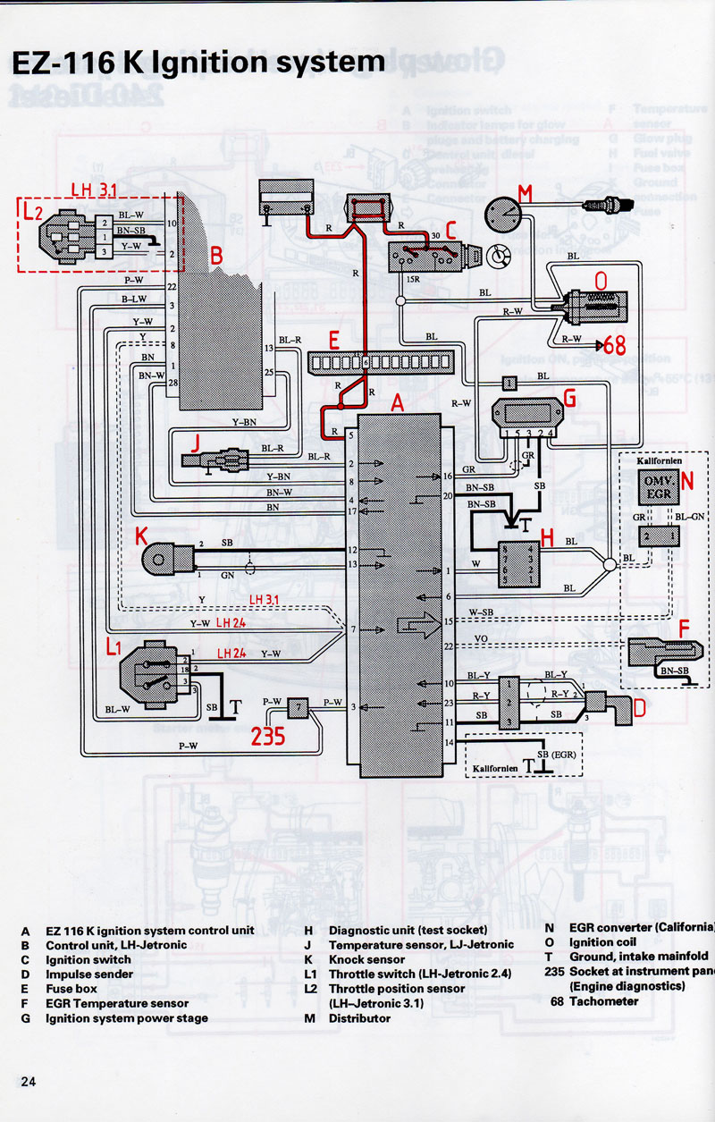
Pull the EZK board out of its box. Connect it. Get your DMM or test light ground reference securely clipped to a trustworthy ground. Verify you have battery during ignition switch on (and cranking) on the board itself pin 6 (blue) and on pin 5 (red). Verify you don't have it on pin 20 (brown/black).

Checking power to a device ought to be the first step, but all too often its the last. And yes, the gray wire's shield is single-point grounded in the amplifier module itself.

92wdm24.jpg
 
Last edited:
Hope this works. Its all I've got.

Pull the EZK board out of its box. Connect it. Get your DMM or test light ground reference securely clipped to a trustworthy ground. Verify you have battery during ignition switch on (and cranking) on the board itself pin 6 (blue) and on pin 5 (red). Verify you don't have it on pin 20 (brown/black).

Checking power to a device ought to be the first step, but all too often its the last. And yes, the gray wire's shield is single-point grounded in the amplifier module itself.

92wdm24.jpg

Thanks. I'm pretty sure the EZK is getting power as the on-board diagnostics are working fine, but like I said I'm willing to try anything at this point. I'll try this and report back when I get off of work later today.

Like I said, my ONLY other explanation is that some input to the EZK (like the coolant sensor or knock sensor) is giving it bad info which is causing it to withhold the pulsed signal. Honestly I don't know enough about how these computers work to have a more detailed guess than that.

It's just frustrating because this car is super clean otherwise and I paid a pretty penny for it because I've always heard that 240's are some of the most reliable cars ever made. HA! Needless to say, I won't be buying another one.
 
LH 2.4 will run whether or not the ECT or knock sensor are connected. I'm with Art on this one. I'm betting you have a power or ground issue. Or, it is entirely possible the EZK itself is bad. It is rare, yet, it happens. They are cheap used. You are probably looking at $25, plus postage to buy one.
 
I've had ezk computer failure. When it happened I had no signal to the amplifier, known good crank speed sensor, and I verified the wiring. I swapped the ezk with one from another car and that was the problem.
 
Confirm SIGNAL and POWER to the EZK during cranking. You have confirmed the EZK GROUND is good (OBD blinks).

Fire an EZK box at it.
 
I guess this wasn't totally clear, but I already tried a different EZK. This past weekend I picked up a good EK out of a running 1993 245 and swapped it into my car. No change. I also swapped my 561 ECU to the 951 ECU out of the same 1993 245 because they came as a package deal.

I didn't get a chance to perform the aforementioned tests yesterday but I should be able to do them today.
 
Alright gang I finally had some time to test some stuff.

I took the EZK out of its box and plugged it in (as suggested). Tested pins 5 & 6 for voltage both with they key on and while cranking; both had 12V under all circumstances. Also tested pin 20, which did not have 12V under any circumstances. So everything checks out there.

How can I test for the CPS signal at the pins in the EZK? I know it comes in to pins 10 & 23 but I'm not sure how to test it. I ordered a scope that should be here tomorrow or Friday so I can use that to try and diagnose this further.

At this point I'm convinced it has to be something with the CPS signal (even though it's a brand new unit, the on-board diagnostics indicate that it's fine, and passes the resistance test at the EZK connector). If I have time tomorrow I'm going to take the bellhousing cover off to check out the condition of the tone ring. In the meantime, I'm willing to try pretty much anything, so please chime in with any suggestions.
 
No codes. 1-1-1. I also ran the procedure for the on-board diagnostics to test the crank position sensor and it said that it was good, although I'm not 100% convinced based off of that alone.

Just to confirm, you ran the ECU/EZK Diagnostic Test Mode 2 (System Sensor Signal Tests) from here:
https://brickboard.com/FAQ/700-900/EngineOBDCodes.htm#FuelInjectionandIgnitionDiagnosticCodesi
and this step passed
Remove the ignition coil center lead and crank the starter motor; the engine will not start but it will turn over. The LED should go out, then flash 1-4-1 for the RPM sensor. If no code is flashed and the lamp keeps flashing, the RPM sensor is faulty. Reinstall the coil lead and turn the ignition key ON to KPII

Correct? If so, the EZK is correctly detecting the RPM sensor and should be firing the spark output to the Ignition Module. Have you checked for +12v (or so) during cranking on both the coil and the ignition module?
 
Just to confirm, you ran the ECU/EZK Diagnostic Test Mode 2 (System Sensor Signal Tests) from here:
https://brickboard.com/FAQ/700-900/EngineOBDCodes.htm#FuelInjectionandIgnitionDiagnosticCodesi
and this step passed


Correct? If so, the EZK is correctly detecting the RPM sensor and should be firing the spark output to the Ignition Module. Have you checked for +12v (or so) during cranking on both the coil and the ignition module?

Yes to all. I've run the CPS diagnostic probably 10 times now and it tests good every time. I've checked for voltage at both ends of the coil and the pins on the powerstage both with the key on and while cranking and everything checks out fine.
 
How about the ground wire at the ignition module? Do you see +12v when measuring across pins 4 & 2 at the module (key on) or alternately, ~0 ohms pin 2 to battery - post (key off)?
 
How about the ground wire at the ignition module? Do you see +12v when measuring across pins 4 & 2 at the module (key on) or alternately, ~0 ohms pin 2 to battery - post (key off)?

I know that the ground wire (pin 2) on the powerstage connector has ground. The pin has continuity with the manifold ground and the negative battery terminal. And I know that there is 12V between pin 4 and ground (using pin 2 as the ground).

Try a different crank sensor.

I installed a brand new Bougicord sensor that passes the resistance test at the EZK connector and the on-board diagnostics. But honestly I might try a different one anyway.

Just crush it, either that or get a more zen like approach to diagnosing your issue. It's something simple. Nothing to get in a tizzy about.

People keep saying this, but I have done literally every 'simple' thing possible along with plenty of stuff I would not really consider 'simple'. In my 12 years of working on cars this is the hardest diagnosis I can remember in a long time.

And if your primary mode of transportation was not working for 3+ weeks for seemingly no reason, forcing you to ride your motorcycle in 30-40 degree temperatures, you'd be in a 'tizzy' as well. So if you don't want to actually contribute to the technical discussion about the issue, please keep the commentary to yourself.
 
Here's some unofficial diagnostics to check the wiring at the ignition module (power amplifier). I just measured these on my working LH2.4.

Unplug the connector from the ignition module, and then measure at the pins of the connector with the key in run position (just touch the meter probes lightly to the connector pins, don't shove them into the connector and destroy the pins).

Measure voltage from the battery ground post to each connector pin:
- pin 1 (coil) ~11.7v (or whatever your battery is at)
- pin 2 (ground) 0.02v (slightly above ground due to wiring losses)
- pin 3 (shield) ~0.02v
- pin 4 (power) ~11.7v (or whatever your battery is at)
- pin 5 (EZK spark signal) 0.23v
 
A test lamp should be used to confirm your power and ground circuits are intact. NOT a meter. One strand of wire can show as 12V on a meter or close to 0 ohms resistance, but the circuit will not operate.

Since the OBD 2 blinks out EZK codes, that tells me you have good power and ground to the EZK. At least during KOEO (Key On, Engine Off).

You have checked resistance on the crank sensor wiring tip-to-tip and you have reported close to ZERO ohms. OK. They aren't OPEN is all that really tells you.

It was mentioned here a couple times to inspect the crank sensor wiring terminals on the body harness side. Terminals get pushed back or have bad tension and it may get overlooked. I use the correct terminal test probe, or an old male terminal from a spare/dead component and make a terminal test tool. You can drag it in and out of the female terminal and FEEL for a loose terminal.

You have not confirmed good signal INTO the EZK when the issue is present. Don't put much faith in that OBD self test. You could try a meter on AC voltage and see what you get. I am interested to see what you get with the scope.

Just to be clear, I am checking for resistance at the EZK's connector between pins 10 and 23 (the two for the crank sensor) and I'm getting 170 ohms. According to cleanflametrap this is right on the money. So I'm fairly certain that the wiring from the crank sensor to the EZK is good. It all passes a continuity test also.

I have to find time to figure out how to use this scope, which I probably won't until this weekend. In the meantime I'll try using my DMM on AC mode between pins 10 and 23 while cranking and see if it generates anything. If so, that would tell me that there's definitely SOME kind of signal going into the EZK.

Thanks everyone for all your help. I am a mechanical Mercedes diesel guy by nature so all of this stuff is way outside my wheelhouse.
 
Back
Top