• Hello Guest, welcome to the initial stages of our new platform!
    You can find some additional information about where we are in the process of migrating the board and setting up our new software here

    Thank you for being a part of our community!

Controlling speedo with MS3Pro

jlfenton95

New member
Joined
Apr 21, 2015
Location
Brisbane, Australia
Hey everyone,

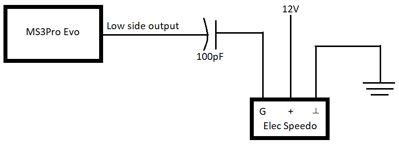
I need some help in regards to controlling the factory electronic speedo.

Car is an 82 244 with MS3pro evo and tremec t5.

Originally had m46 with mechanical speedo. Now with the t5 I am using a Falcon VSS (Australia) which is a 3 wire so I believe signal is square wave, into the ms3pro for logging and whatnot. I want to use factory gauges so my first thought was to use an electronic speedo and use a frequency output to control the speedo. I have since learnt the speed sensor from the lh cars puts out an ac waveform.

So I am wondering if it is possible to control a factory electronic speedo with the ms3pro?

Thanks! :)
 
If you want to use the 1982 factory gauge, you'll need an electronic to mechanical converter box, and an appropriate short speedo cable to match the box and speedo connectors. Something like this:
https://www.dakotadigital.com/index.cfm/page/ptype=product/product_id=886/mode=prod/prd886.htm

If you're OK converting to a later model Volvo 240 cluster with an electronic speedometer, then all you need to connect up the MS3pro is a small series capacitor, which will change the DC square wave into a AC pulse train suitable for the factory speedo. A generic yellow "0.1uF ceramic capacitor" should be fine - pennies apiece, plus $3 shipping.

You'll then set the MS3pro speedo output to 9800 pulses-per-mile, or 39200 ppm (if you have a later ABS speedo). The calibration is the K9800 number on the speedo face.
 
Yes I do want to use a later model electronic speedo. I am looking at using a spare injector low side output to drive the speedo. So this is the circuit you describe?

171993863.sIcw1Sga.diagram.jpg
 
I looked at cleanflametrap's speedo schematics here, and it's a little more complex to convert from MS3pro to a suitable 240 speedo VSS signal. This should do it:

MS3pro-to-240-speedo.png


The 1K pullup resistor is needed if you're using an open-collector output pin on the MS3pro. It can be skipped if you're connecting to a logic-level output. The 1.0uF capacitor can be mounted by the MS3, or by the speedo, whichever is easier. The 10K resistor goes across 2 of the speedo connector pins and is probably easiest to add near the speedo connector.
 
Awesome. How you came to that conclusion is above my head lol. I have plenty of spare logic level spark outputs available so that makes life even easier. However just reading the manual:

"max logic current is 200mA";
and "Unused ignition outputs may be used as on/off outputs, although their low current capacity means we do not recommend using them for anything other than logic level devices or LED lights. Do not use these outputs to drive relays directly or use them for anything that needs a ground for triggering."

Does either of these apply to the speedo circuit?

And confirming, you meant to change the capacitor value from 0.1uF in your first post to 1.0uF as above?
 
If you use a "spare injector low side output to drive the speedo", you need the 1K pullup resistor. If you use a "spare logic level spark output", you can skip the 1K pullup. The speedo circuit only draws ~5mA so it will be fine. And yes, I waffled and decided 1.0uF might work a bit better at low speed.

I'd certainly try the electronic speedo on the bench or passenger seat before installing it permanently. You should be able to find a MS testmodes menu to pulse the MS VSS output. With a K9800 speedo, a pulse rate of 165Hz or 6.1ms, should show ~60MPH.
 
Roger roger. I guess I should track down a speedo somewhere around here then. Thanks for all your time and effort. I'll report back here about how it goes,, if I remember...
 
Back
Top