Fill in the roof?....weld it? Epoxy?
Oval Min cross sec. area is where, exactly? I have my own ideas. I'm interested in yours.
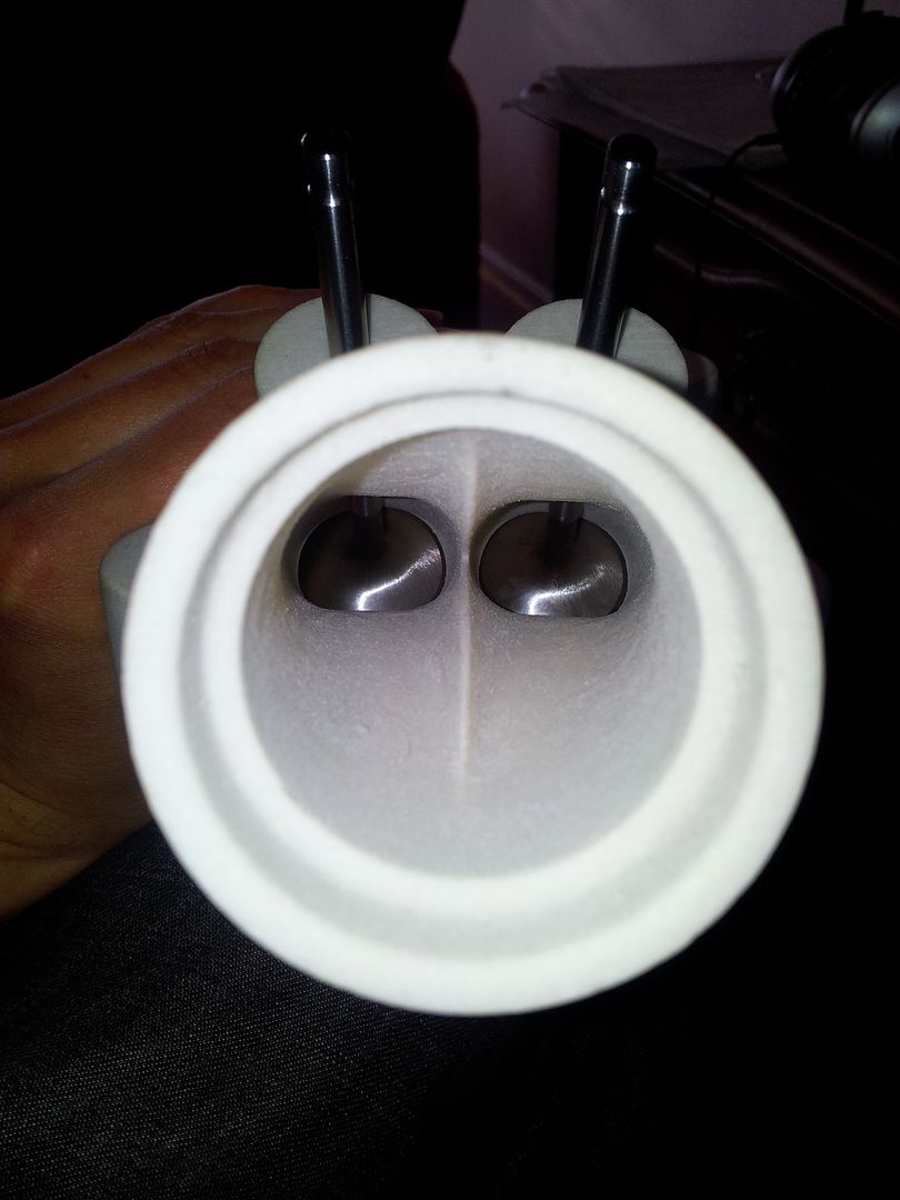
What is your idea of an ideal bowl to seat transition?
If you have pictures, that would be great!
Surprised? Not the first one then

I use epoxy, Scotchweld 2216 aerospace stuff, good against both alcohols and hydrocarbons. Its sandable and machineable, but still kind of rubberish so it expands and contracts with the material in the head.
I usually never base my ports on a minimum diameter in the seat... the seat insert is just a harder metal part to be wear resistant. The seat has to be round and cut by a Mira or similar, the rest before and after can be at your peril, the cutter don't HAVE to decide the shape and lesser diameter of the seat insert, if so was the case F1 and such teams would REALLY struggle.
I decide upon a mcsa area to provide the flow needed for the application, whatever maximum power is desired I maximize the valve size non the less. Two mcsa's of equivalent ?24mm flows to provide 239 cfm at 28"h20, for the 262 head two mcsa's of ?32mm would be good for in the range of just over 400cfm. Usually at a velocity that is supposed to be "impossible". So why dig a massive hole?
Regarding the position of the mcsa i decide upon a 7? (ish) taper from the chosen mcsa size to the inner radius of the seat angle cut (as if it was inline with the stem) then make it oval, straight down on the side walls and tapering (along a curve for instance) in the roof and floor. Works just about everytime
")
If you get for instance 380cfm from this type of venturi/pressure recovery type port, it'll flow in the running engine like a 418ish cfm regular port (factor of 1.1:1 aprox), but with the advantage of the higher velocity (more bottom and middle grunt).
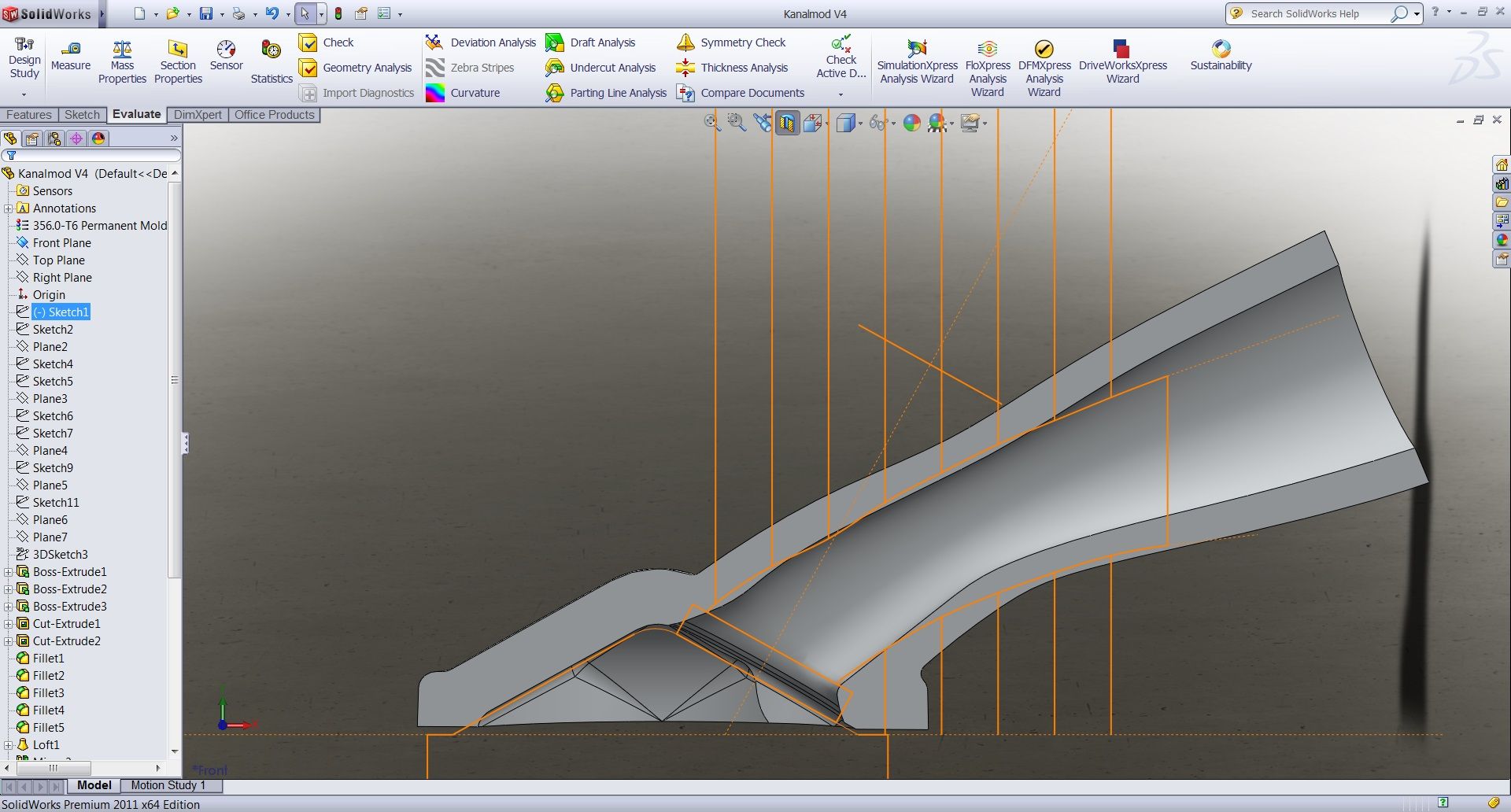
In aiding to design such things i use CAD software, can be done manually, but more hassle.
The example is from a whiteblock head for my new daily driver, as I'm still doing R & D on a 262 head I got hold of a week ago...
The bare model like this (I use rapid prototyping, but no worries the orange outlline is stock port, so it mostly fits inside it...) only flowed 215cfm as the shape is on the model, some incredible minor adjustments and it got 239cfm (not too impressive? concider the factor of 1.1:1 i mentioned earlier
) @ 12mm lift on 2x 34mm valves, point beeing mcsa limited. I won't tell the details, as I don't want to post a blue print to be copied... The port will support more with slightly larger mcsa and some more lift, beneficial in forced induction applications where the velocities will be high anyway...
Revealed too much "best of holding it for yourself" stuff already I guess


