• Hello Guest, welcome to the initial stages of our new platform!
    You can find some additional information about where we are in the process of migrating the board and setting up our new software here

    Thank you for being a part of our community!

93 244 cluster problem

RickATL

Member
Joined
Jan 21, 2015
Location
Atlanta
Still dealing with the ramifications of trying to install keyless entry and having moded the cluster at the same time. Now i dont know what is causing problems where. Cluster is doing all kinds of things. Turn signals flashing on opposite sides, speedometer bouncing, turn signal dash lights stay lit up, etc.... I unplugged the keyless and im still having problems.


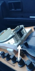
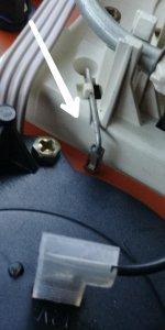
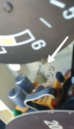
Does anyone know what this thing is? I took the cluster out of my 91 wagon. It has the same metal rod at the speedometer, but it is flat against the plastic. Im guessing i snagged this thing at some point messing around maybe.


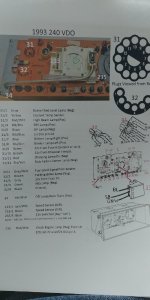
I dont see it on the green book diagrams.
 

Attachments

  • PicsArt_04-11-05.50.55.jpg
    PicsArt_04-11-05.50.55.jpg
    43.2 KB · Views: 78
  • PicsArt_04-11-05.42.43.jpg
    PicsArt_04-11-05.42.43.jpg
    47.5 KB · Views: 76
  • PicsArt_04-11-06.11.35.jpg
    PicsArt_04-11-06.11.35.jpg
    114 KB · Views: 78
I don't know what that wire loop is, but I'd guess that when you moded the cluster for larger bulbs, that you damaged or cracked a trace on the inside of the circuit board. You'll need to remove the speedo, then remove the circuit board (temp/fuel gauges will still be attached).

Inspect carefully around the moded bulb openings. A bright light and a magnifying glass helps. You're looking for thin cracks around soldered pins/wires, and thin cracks in the traces. If you're good at soldering, you could just reflow all the joints (use 60/40 tin/lead solder, the lead-free stuff is harder to work with and harder to inspect).
 
It is just a solid wire jumper going from that connector on the main cluster circuit board to an identical connector on one of the 2 circuit boards on the speedometer. Just pull the speedo out and make sure it plugs in properly when you install the speedo. You didn't line it up when installing the speedo. The opposite circuit board has three similar connectors that have to seat on pins coming from the main circuit board. IOW, you have to line up 4 pins total while lowering the speedo into the back half of the housing.
 
Thanks. I dicovered that some have 4 pins + that (1) so 5 total. They are all pins that have to slide into the sleave just right.


For those folks researching. My 93 240 has 4 pins, this video shows an older cluster that i dissessembled for reference. Here is a 14 sec. video showing how the three pins line up. https://youtu.be/y44MK9tUwjA

The picture below shows where the pin on the other side comes through.
It is just a solid wire jumper going from that connector on the main cluster circuit board to an identical connector on one of the 2 circuit boards on the speedometer. Just pull the speedo out and make sure it plugs in properly when you install the speedo. You didn't line it up when installing the speedo. The opposite circuit board has three similar connectors that have to seat on pins coming from the main circuit board. IOW, you have to line up 4 pins total while lowering the speedo into the back half of the housing.
 

Attachments

  • PicsArt_04-12-09.28.14.jpg
    PicsArt_04-12-09.28.14.jpg
    63.3 KB · Views: 48
I knew the speedometers were different (even same year models sedans vs. wagons,) what i discovered was that the circuit boards are also different. Different numbers of pin connectors, plastic moldings for the speedometers, other electrical parts i dont know the name of....
 
I don't know what that wire loop is, but I'd guess that when you moded the cluster for larger bulbs, that you damaged or cracked a trace on the inside of the circuit board. You'll need to remove the speedo, then remove the circuit board (temp/fuel gauges will still be attached).

Inspect carefully around the moded bulb openings. A bright light and a magnifying glass helps. You're looking for thin cracks around soldered pins/wires, and thin cracks in the traces. If you're good at soldering, you could just reflow all the joints (use 60/40 tin/lead solder, the lead-free stuff is harder to work with and harder to inspect).

That diagonal wire plugs into the speedometer unit as it is connected to the Service Reminder Light which is suppose to illuminate every 10K miles. It is reset by pushing the dip switch up on the back of the cluster either manually or via the push button on the front right corner of the instrument cluster. You have to remove the temp and fuel gauges as well to separate the circuit board from the inn plastic housing to access the circuit board and the traces.

I looked at my original 1989 "testbed" for this mod (blue arrows) as well as disassembled a 1992 circuit board to see if any circuits would be near the bulb openings which they are not. As for reflowing the solder joints, that could be a prime suspect, but don't believe filing out the opening for the bulb mod would be the cause of the issues being described.
 

Attachments

  • IMG_2034.jpg
    IMG_2034.jpg
    100.6 KB · Views: 32
  • IMG_2035.JPG
    IMG_2035.JPG
    77.3 KB · Views: 32
  • IMG_2036.jpg
    IMG_2036.jpg
    99.9 KB · Views: 32
Back
Top