• Hello Guest, welcome to the initial stages of our new platform!
    You can find some additional information about where we are in the process of migrating the board and setting up our new software here

    Thank you for being a part of our community!

The (build) story of a Greek (hopefully fast) 240 brick

Gary you definitely should drive it next time. Or i have to make you in some way :oogle:

Just a fun fact.. If the machine shop makes the rings 2.5mm out of INOX, you get a swollen finger if you want to get it to sand it by hand down to 1.3mm. It really helps having it at this size putting new seals and pump in place, but i am not sure what the swollen finger can be useful to :-P
 
Well, in my case id and od were correct..but the ring was taller than it should, to allow me to install the pressure pipe without bending it.
 
The story continues from post #112

The front engine view that will be hidden by the radiators. Looks nice this way (and .. more complicated than stock) despite it is not complete !


Update 09/02/2022

It has been a long time since the story was updated, however the progress has been really slow through all this time ! Hopefully it will progress a bit faster now.

  • Condenser swap: Since a new compressor was chosen, a new more efficient parallel flow condenser was mandatory. The model that was chosen was Climaparts CNFP1624 which is sized 16"x24"x20mm.


    The old SPAL pusher fan was used, however it was mounted on the condenser on the side that is in line with the radiator's fan hole, so it transfers less heat on the cooling system. Also the fan was mounted in a distance from the condenser core so that the vibrations won't punch any holes on the delicate aluminium core.


  • Blown recirculation bellow & heater core replacement: Since the whole A/C system is updated .. the recirculation bellow had to be fixed. It was blown due to the vacuum check valve fail so the 2bars of turbo pressure went through. Because the dashboard was out it was an opportunity to clean up the evaporator (cleaned outside and flushed internally), change the heater core to a new one (just in case), a new blower motor and blades, and resistor .. a complete HVAC box overhaul in a few words.

    The source of all troubles:


    Demolition time:


    Finished product:


    Why not replacing the engine's firewall insulation with something that will keep the cabin quieter and cooler ?


    Back together:


  • Dashboard cracks fix: The dashboard was cracked in several spots, so .. why not trying to improve its appearance? Maybe it will crack again, but for now the result is good. Two of the cracks were huge, which turned out that these were the easiest to fix. On each side of the crack a 2mm hole was drilled so that they won't keep opening up (in theory). Toilet paper never tears correctly at the perforated spots .. so why would a dashboard crack? :rofl:


    The weatherstrip adhesive was used to fill up the holes, while the vinyl repair kit was used to touch up the fixes.


  • Heater Valve: The old heater valve (which also featured a compensation coil) would not seal up perfectly, so it was replaced with the one that Wagonmeister sells. Perfect product well documented kit and a great guy. Always happy to support him!


Continued at post #130 --->LINK<---
 
Last edited:
The story continues from post #129

Update 30/8/2022

  • Rerouting A/C Lines: The nastiest thing to see in the 240's engine bay (and also makes life difficult for doing things on the engine) is the thick A/C return line that was routed over the engine. The main idea behind the modifications made was rerouting this hose along with updating the system to r134a (hoses, o-rings, compressor, drier etc). Apart from the need to build new A/C lines which are longer since they go around the engine bay, the stock windscreen washer bottle had to be dumped since there was no space for them to be routed past it. The stock bottle was cut and shortened, but it is made out of Polyethylene which was proved that can not be melted to stick, there are no glues to be watertight, so another solution has to be found. The stock bottle has a very unique shape which is difficult to be copied in an aluminium construction, can not be 3D printed since it is not watertight, so this problem may be proved one of the weirdest on the project given the tight space due to the intercooler's outlet hose. Still working on it ..


    New type r134a expansion valve. Never bothered to adjust the old one.


    A trinary r134a valve was added which provides 3 functions: (a) has a fan switch that turns on/off the fan automatically depending on the coolant pressure (b) can disengage compressor if overpressure is detected and (c) disengage compressor if low pressure is detected.


    Before installing the dashboard back in the car, a good vacuum was pulled to see if there are any leaks. Fingers crossed everything is good.

  • A/C RPM Switch: To make sure the new compressor won't be shot if forgotten on during any unexpected road battles, a dedicated adjustable RPM switch was bought from this nice guy: https://www.ebay.co.uk/itm/332825134965. It was installed in series with the stock thermostatic switch and will disengage the compressor's clutch in given RPMs, so this will act as a compressor rev limiter.

A note related to the new (very nice) Turbobricks forum (great job Dana!) & to this thread:

The new forum allows the posts to include up to 20 images and/or 10.000 characters. The way I followed till now was to edit the old posts and add up to 50 images which was the older system's limit which also probably had no limit to characters. So now I will follow the new system's limitations and use a new post for each update. This will be probably easier to read and comment.


However, I can not correct some little mistakes which were spotted into the older posts (due to the data transfer into the new system). For example some ' or " characters appear like question marks. Also the my photobucket account is now closed so some images in the replies may not be displayed correctly and the link in the first post is no longer working. Only Flickr from now on.

Finally, the last (big) post (#112) was split into 3 different posts (#112, #129 and 130) just to test this new function and be able to include links for the new updates (as usual) in the end of each post.


Continued at post #136 --->LINK<---
 
Last edited:
Nice little update there Aris!

Curious what you end up finding on the fuel system fiasco once you get all that resolved as well.

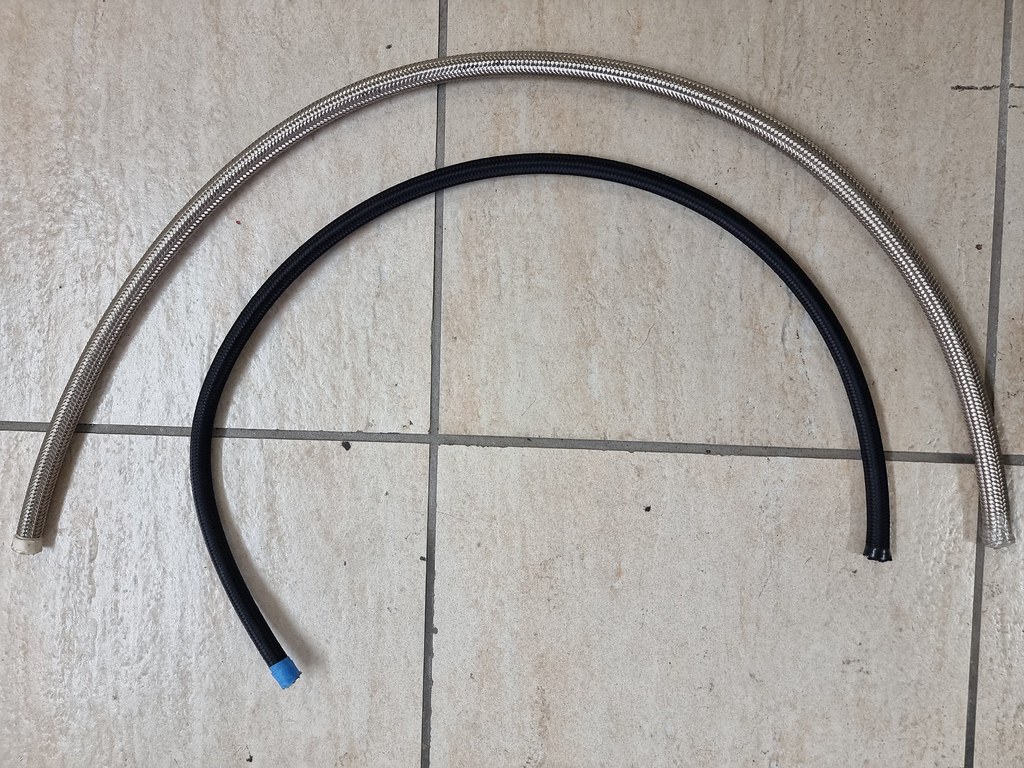
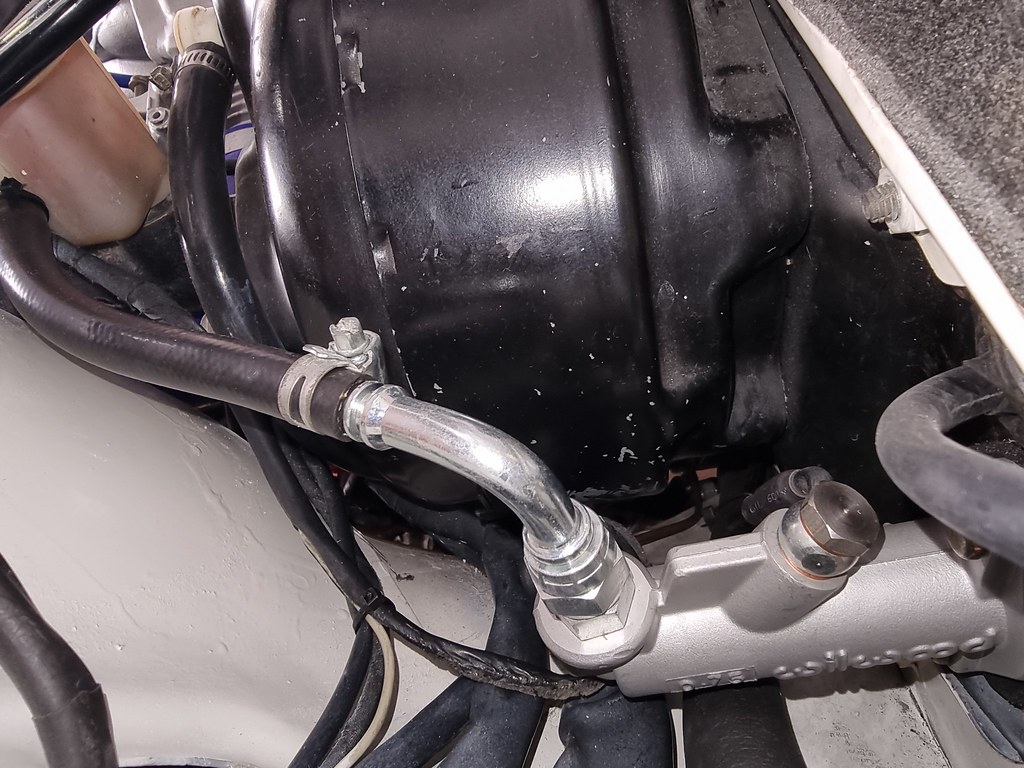
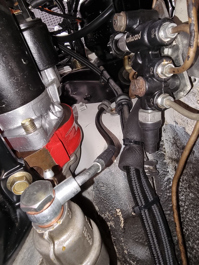
Now that you mentioned it .. a word of advice for anyone using braided AN hoses for fuel delivery system:

PLEASE DO NOT USE THIS SHIT FOR FUEL DELIVERY !! YOU WILL WASTE YOUR MONEY .. ASK ME HOW I KNOW.

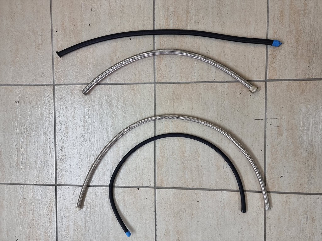
So .. long story short, as you may have seen in the past, Aeroflow braided AN hoses #8 for engine feed and #6 for return to the tank were installed. These lines have been on the car for 5-6 years, while the last 3 years they were drained from fuel due to the rebuild of the engine.

The last week after assembling almost everything on the car, it was decided to pour some 100 RON fuel in the tank and turn on the pump to prime the fuel system before turning the key, to check for any leaks.

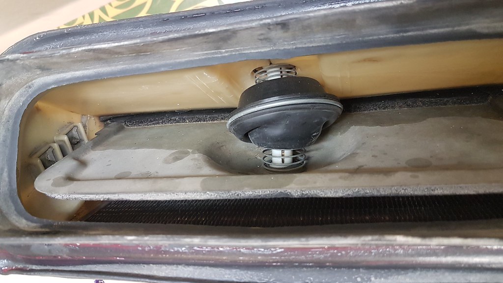
Surprisingly, the fuel never made it past the 3 bar FPR because 2 out of 4 meters of the line were literally turned into a kitchen strainer. Fuel was squirting everywhere, flooding the garage. Such expensive lines were useless! Of course the return line when pressure tested was leaking like crazy as well. How do the stock fuel lines last for 50 years and these got wasted so soon ??

After contacting the seller and many others, it was found out that the hoses life count starts when they first get wet with fuel, and stops anywhere between 2 to 6 years no matter if they are being used or are full of fuel or are drained. Of course these can not be used with ethanol or any other "difficult" fuel.

The only thing that made the situation a bit better was that the lines kind of "vaporized"/cracked internally and did not produce any small pieces to block the filter-fuel rail-injectors etc.

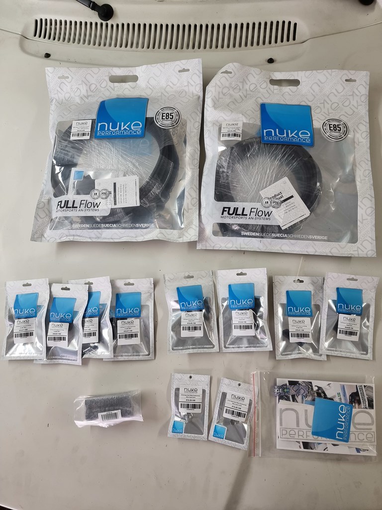
So now PTFE lines and new hose ends (since they are not compatible to AN fittings) from NUKE are ordered.

Damn .. always something before the "big" moment !

Fingers crossed they will last a bit longer .. as everybody advertises ...
 
The story continues from post #130

Update 17/11/2023 (a bit delayed)
  • Replaced fuel lines with PTFE: As mentioned in post #133 all the fuel lines had to be replaced because the AN hoses failed badly. The new ones were ordered from NUKE, as well as new hose ends since the PTFE hoses are not compatible with the AN hose ends. The NUKE lines look of very good quality, they have nylon braiding outside of the stainless steel braiding so they don't scratch things, and they are much thinner than the AN lines and they are black. Also the guys fron NUKE are very nice and helpful.
The old lines that failed:​
NUKE setup:​
Comparisson between the two setups:​
  • Replaced the clutch master cylinder: The problem was discussed in this THREAD in detail. In short with the new clutch-flywheel setup, the old 740's master - slave cylinder cobination would not allow the full disengagement of the clutch, so the gears would not change easily. So the master cylinder was replaced with one by Wilwood with more piston travel at the same bore (part no 260-6089). Of course it needed a new line which was custom built, and some more parts. The mounting on the pedal was done by altering a 264's setup which now allows to adjust the pedal's height. The slave cylinder remained the same.
The old setup (740):​
The slave cylinder kept unchanged:​
This is how the required extra travel was calculated in order the clutch to disengage. The nut could change the total pin length:​
Part of the pedal assembly taken from a 264. The front part was removed, but the U shaped piece did not have the same thread as the new wilwood rod. So it was welded-drilled-tapped to match the threads:​
  • Added 2 rear seatbelts. No pictures here but anyway this is not very interesting..

Continued at post #137 --->LINK<---
 
Last edited:
The story continues from post #136

Update 28/02/2024
  • Added rear power windows. No pictures here .. not really interesting.

  • Intercooler (IC) Water Misting System DIY & Washer Tank Relocation. This seemed to be a good idea since in Greece temperatures are generally high, so a misting system of this type could possibly benefit performance, without too much hussle. Another option would be water-methanol injcection but since it is a generally unstable fluid, expensive and needs much more than just plug and play procedure (since water-methanol is sprayed in the engine and not externally - and so ECU remapping) this was out of the question. In contrast, the IC misting system is something cheap (in the way it was done), easy to deal with and of course it feels like a TBs approved method ! The system design was found online (https://strikeengine.com/intercooler-water-sprayer-diy-the-parts-you-need/) and was modified it a bit to fit this project as stealthy as possible.

    To relocate the washer tank in the rear (no more space in the engine bay due to the new A/C compressor lines), a custom bracket was used as well as pieces of hard rubber to make the whole construction as rigid as possible and not move at all under the weight of the water (one piece of rubber was inserted under the bottle tray and one behind the vertical part of the bracket to the side wall of the butt cheek). Keep in mind that vibration in the rear is more intense compared to the engine bay's.


    The setup was as following:


    1. T-Piece: To tee into the washer jet line just after the windscreen washer bottle (no need to install separate tank - 4+ liters of the stock washer bottle must be ok).

    2. Pump Hose: To connect the washer tank to the pump.

    3. Pump Fittings & Adapter: To convert the fitting on the water pump's inlet to a barb of 6mm diameter and the outlet to push fitting, 1/2 BSP to 6mm.

    4. Diaphragm Water Pump: Diaphragm pumps are excellent because they will constantly monitor line pressure and when it drops below a threshold will activate to build back up pressure. Constant pressure in the line is needed so when the jet is activated, atomised flow immediately is achieved. Diaphragm pumps can also supply high pressures, 30 psi is the minimum but up to 60,70 PSI+ is better. The water needs to be misted before it hits the intercooler. In order to hide the pump assembly the fuel pump-pressure regulator bracket under the car was used.


    5. Rigid Plastic Pressure Hose 6mm (external diameter). This is the kind of hose that is used in the water feed of the home freezers to supply water, or in misting applications.

    6. Water Filter: Mounted before the solenoid switch. Push fit fittings, 6mm diameter.

    7-8. Solenoid Valve with female fittings to convert the solenoid fitting to push fittings (1/8 to 6mm), directional, 12v. It was installed as close as possible to the nozzles to be able to have instant delivery of pressure without the need to fill the whole line with water.


    9. Misting Nozzles 0.6mm and and triple adapters (120 degrees nozzles placement): The smaller the nozzles are, the more unreliable, 0.6mm is a good compromise. The intercooler doesn't need to be bathed in water, it should get as thin as possible film of water on it. The water needs to be able to vaporise off the intercooler's metal as easily as possible, so the water should be in the form of mist on it (not sprayed) which would evaporate quickly and suck heat out of the intercooler. Water sitting on the intercooler will get warm and linger on the fins reducing the effectiveness of the water.


  • Control of the misting system: This was a real challenge because the controls should be out of sight but in the same time easy to use in the heat of the battle. Since this car is a sedan, it has no rear wiper, so this seemed a good opportunity to use a wagon windscreen wiper switch which has lots of functions on it.


    As it was proven however, this switch has a really complex 10 electrical contacts/5 cables design in it, which made it too difficult to adapt it to the project. However after hours of testing with a multimeter (it was not taken apart for obvious reasons) the following electrical connections diagram was "invented":


    SV=Solenoid Valve.
    P=Pump
    Note the presence of the 2 diodes which are needed.

    The outcome:

    - Switch is in off position: Everything is OFF. As long as button is pressed solenoid valve is energized but nothing happens since pump is OFF.
    - Switch is in left position: Constant misting (pump and solenoid valve both ON). Button makes no difference if pressed.
    - Switch is in right position: Pump is ON but no misting since the solenoid valve is OFF (line is pressurized). When button is pressed solenoid valve turns ON as long as it is pressed (misting while button is pressed).

  • Low water indication: The washer tank should never be empty, since this would probably hurt the pump, so a non-contact sensor was ordered which will be wired to a dashboard unused bulb to turn on when the fluid's level is low. A float switch will be avoided if possible because holes on water tanks of this type never seal well. Here are different types of these sensors which look promising for many applications and can be ordered from AliExpress: https://www.xkc-sensor.com/product/feijiechushiyeweichuanganqiykm.html
 
Last edited:
Back
Top