• Hello Guest, welcome to the initial stages of our new platform!
    You can find some additional information about where we are in the process of migrating the board and setting up our new software here

    Thank you for being a part of our community!

Need Help with Volvo 240 Engine harness to body 9 pin connector

saffy4052

New member
Joined
Aug 17, 2011
Hey guys,
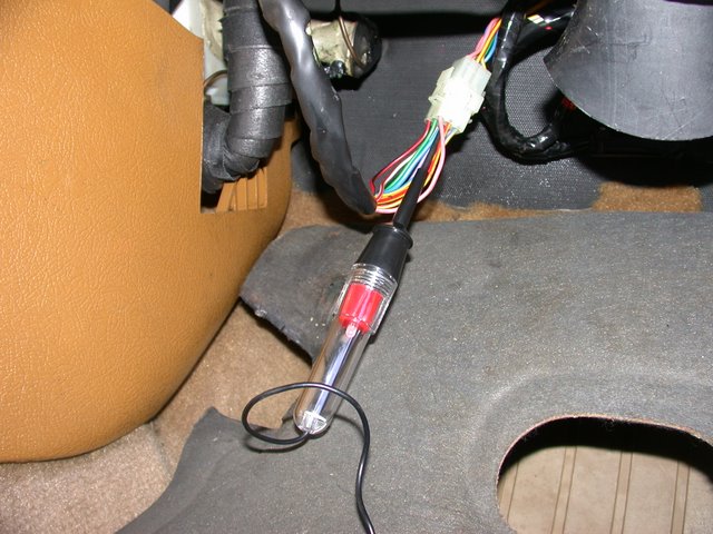
I am working out the wiring for a 5.0 swap into my 1990 Volvo 240. There was a white 9 pin connector that looks like it connects the volvo engine harness to the body/dash. Does anybody have the pinout for this connector? Here is what the wires look like coming out of it on the engine side of the connector.

---------------------------------------------------------
|Blue---------------------|White/Red----------|Yellow/Red (much thicker)
|Crank+Run?--------------|Tach?--------------|fuel pumps?
|-------------------------|--------------------|
---------------------------------------------------------
|Green-------------------|Blue/Black----------|Purple
|-------------------------|--------------------|
|-------------------------|--------------------|
----------------------------------------------------------
|2 Pink Wires-------------|Yellow/Red----------|Blue/Yellow
|Crank?------------------|fuel pumps?---------|
|------------------------|---------------------|
--------------------------------------------------------------
 
So I think I have figured out a bit of it...

2 pink wires I believe are check engine light
Thin yellow/red is the lambda sensor heater power
Blue/Yellow is crank
Blue is run + crank
Thick Yellow/Red is fuel pumps
 
Here is the pin out from the Electrical Chapter of 'Volvo's That Run'.

http://forums.turbobricks.com/showthread.php?t=250604

I have found there is no definitive pin number relationship from year to year. Follow the wire color code. I see that your connector is entirely different from what I found/created. I added several wires through the connector that you will need also. I have several spare male and female connector pins if you need some. I even have a couple of the connector bodies if yours come apart from age or abuse.


Volvo Body Connector

The Volvo Body Connector (VBC) provides the following circuits to/from the body. Because I chose to add several circuits between the engine and body and the fact that I crushed my connector on one of many engine installation efforts I replaced the Volvo connector with a water resistant marine 8 pin connector.


Pin 1 - Oil Pressure (black) connection is to C115M pin 26 (DG/WH) which connects within the Ford wiring harness to the oil pressure sensor to operate the oil pressure light on the instrument panel.


Pin 2 - Temperature (yellow) connection is to C115M pin 16 (also YE) which connects within the Ford wiring harness to the temperature sensor to operate the temperature gauge on the instrument panel.


Pin 3 - Alternator (red) connection is to C115M pin 41 (LG/RD). Volvo ignition switch supplies B+ through the instrument panel alternator light.


Pin 4 – Brake light voltage is extended to C115M pin 4 to unlock the torque converter lockup upon application of brakes.


Pin 5 – Tachometer connection to C115M pin 2 to provide a signal to the Volvo instrument panel tachometer. This invokes the issue of an 8 cylinder signal driving a 4 or 6 cylinder tachometer. See the speedometer / tachometer chapter


Pin 6 – Check engine or Malfunction Indicator Light (MIL) or Lamda light is connected to C115M pin 6.


Pin 7 - Ignition Start (blue/yellow) connection provides B+ from the Volvo ignition switch through NCF #6 and MINI fuse #11 (10A) to the operating windings of the START relay.


Pin 8 - Ignition Run (blue) connection provides B+ from the Volvo ignition switch through NCM #3 and MINI fuse #9 (25A) to the base of the PCM diode. It should be noted that the Volvo ignition switch is only supplied by an 8A fuse in the Volvo fuse panel. That will have to increased to 25A to meet the current requirements of the Ford end of the RUN circuits. That does nothing to address the wire size to/from the switch or the switch contacts. The proper way to handle this is to install another relay in the BJB to upgrade the current capability but I am too far down this road to back up now. I will post the solution when the smoke escapes.
 
This 9-pin connector?

harness063.jpg


I think you had what you had correct. Added to that are:
gray/red (not white/red) senses AC switched on.
green senses AC compressor on.
violet runs shift indicator light -- tied back in automatics
blue/black brings VSS pulses from speedo to ECU
 
Thanks cleanflametrap, that is exactly what I was looking for.

Update; here are the wires coming from the mustang wire harness that I need to connect into the Volvo Body
Oil Pressure
Water Temp
Tach
HEGO (lambda) power (Found it, thin yellow, red)
Fuel Pump relay power (Found it, thick yellow/red)
Fuel Pump relay ground (not a problem)
2 wires (to and from) the neutral/clutch sensor circuit
Crank + Run (Found it, blue)
Crank (Found it, yellow/blue)

So my next question is, where does the water temp, oil pressure, and tach wires run through the firewall? And where would be the best place to tap/splice into these?
 
So my next question is, where does the water temp, oil pressure, and tach wires run through the firewall? And where would be the best place to tap/splice into these?

I think post #4 has that info, but I also wonder if there is perhaps another forum on TB where the performance upgrades such as yours are commonly done. I'm just a fixer of plain old stock 240s for my family.
 
Back
Top